Relay question

Homebrew Talk - Beer, Wine, Mead, & Cider Brewing Discussion Forum

Help Support Homebrew Talk - Beer, Wine, Mead, & Cider Brewing Discussion Forum:

This site may earn a commission from merchant affiliate links, including eBay, Amazon, and others.

SookeBrewing

Well-Known Member
Joined
May 20, 2011
Messages
69
Reaction score
8
Location
Sooke
Hi all, as you may know I am working on a Kal build, and I bought some relays that another HBT user went with that were much cheaper (and enclosed which I liked).

I'm just curious about how to wire these things, since they look different than the Kal ones.

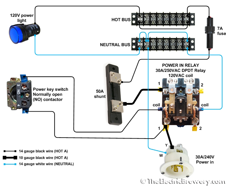
Is the picture below pretty much the way it's done? It looks similar, as far as the orientation of the terminals on my relays.

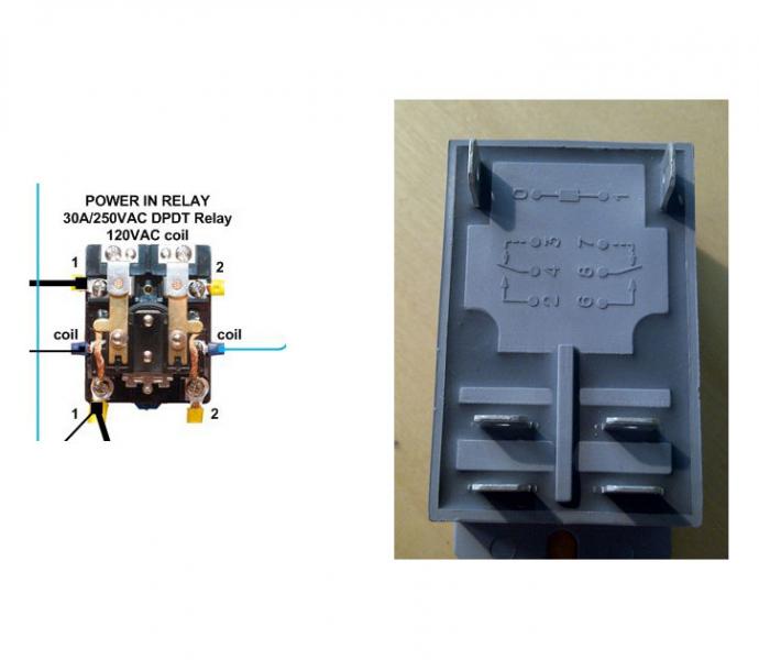
ie, is the wiring diagram on the left, how I would connect mine on the right?

attachment.php


Thanks!

relay.jpg
 
Hi, not sure what you're asking? The coil is terminals 0 and 1. The DPDT switching NO/NC action is on the remaining terminals.

eta .. hm I can see, that is a bit confusing, the engravings on the plastic show DPDT but there are not enough terminals there. I suspect only the NO contacts have terminals.
 
Ok, the terminal layout would match a DPST relay. I suspect they use the same housing for a DPDT version too. So still 0 and 1 are the coil, and then 2 and 4 close when energized, and 6 and 8 close when energized, and the NC 3 and 7 do not exist. Usually that would be used in the U.S. for 240VAC switching.
 
Ok, the terminal layout would match a DPST relay. I suspect they use the same housing for a DPDT version too. So still 0 and 1 are the coil, and then 2 and 4 close when energized, and 6 and 8 close when energized, and the NC 3 and 7 do not exist. Usually that would be used in the U.S. for 240VAC switching.

Thanks - I think I understand now after doing a lot of reading about relays last night. That is half the reason I'm doing my own panel, I love learning about this kind of thing.

power.jpg


So, does it matter which sets of terminals I use to connect to the parts of the brewery? On that diagram above, the coil is connected to the switch and the neutral bus, which makes sense since that is what is activating the coil. The other sets of terminals are connected to the 240V receptacle and the hot bus (through the 50A shunt). What I'm wondering is does it matter which set of terminals (2 and 4 or 6 and 8) that I connect to?

Thanks!
 
Hm well I think that looks ok for powering the coil.

There seems to be some things missing in the diagram.

The power in says 240VAC, I'm assuming that is the standard 120VAC 'split phase' with two hots that you're getting the 240VAC from.

So if you also need 120VAC for control power you need a plug/receptacle that carries the neutral - not all plugs do that, if it's only got three prongs, it's probably two hots and a ground, not a neutral.

Ok so if the assumptions above are right, I'm assuming also your load will be a heating element 240VAC taking two hots (I'm not sure if that is what the 50 amp shunt is supposed to represent?). So you would use one contact (2 and 4) to switch one of the hots (L1), and the other contact (6 and 8) to switch the other hot (L2). That way you open all ungrounded conductors when you interrupt the load.
 
This relay is for the power in. The receptacle you see it connecting to is a 4-prong 240V in coming from a 4-wire dryer cord plugged into a standard 4-prong dryer outlet protected by a 30 amp GFCI breaker. This relay is to power up the system. The switch that is connected to the coil is a keyed selector on/off, and turning it powers up this relay which sends power to the whole panel. Not shown, to the left of the main power relay above, are the other two relays for the 2 heating elements. The 50 A shunt is for the amp meter in the panel. I think I get it now, it shouldn't matter which set of contacts I connect to, since they are both energized when the coil is activated, and de-energized when the coil is deactivated.

Thanks again,
 
Ok that makes sense. I think all that missing then is L2 or what your dwg might call HOT B (since it references HOT A so far). So that might be say a red wire from your receptacle going through the contacts on the right side of the relay (I assume those are the '2') connections, and then going to a hot bus for HOT B. So that way your main power relay truly interrupts both hots when it is de-energized. The 7 amp fuse I'm assuming is there for maybe using that bus for running your pumps or something (but not for feeding the relays for the heating elements).
 
The diagram is Kal's, and he uses it for a step-by-step guide at electricbrewery.com. Yes, it does not show the second hot as it that was connected at a later step. The 7A fuse before the hot bus protects the 14 gauge wire he uses to run the 120V components.
 
Back
Top