
blackheart
Well-Known Member
Hey guys, we are working on two new fermentation freezers to hold our new Brewhemoth conicals.
We have very similar Kenmore standing freezers to what deep six did here.
https://www.homebrewtalk.com/f51/my-new-fermentation-cabinets-66926/
However, we have a digital controller on our model and it appears the wiring is slightly different. Let me tell you what we are trying to do and hopefully we can figure out how to do it.
We are trying to make a heated and cooled fermentation chamber, being in upstate NY and needing to do both year round. The cooling is obvious, and we havent decided on the heating method yet, except we will simply have a relay controlled 120v outlet to which we can plug in a heating fan or wrap later.
Ideally the second of two outlets inside the freezer would be constantly on incase we wanted to add something else inside the freezer.
We have two freezers right now, and both are going to be controlled via a BrewTroller control board. We will have one 3-wire connector containing 12v+, 12+, and ground for 12v. One 12v wire will control the compressor for cooling, the other will control the 120v outlet for the heating device. We also will need an internal connection for the temperature probe. This requires a cable with 3 wires.
So the end result of modifying these freezers will be overriding the compressor so that a 12v signal operates the compressor and a second 12v signal enables the internal 120v outlet. Both of these wires are in the same 3pin MIC connector on the rear of the freezer. A standard CAT-5 connector on the rear connects the internal temperature probe to the external BrewTroller box. Inside, the freezer has an internal connector to easily disconnect the temperature probe.
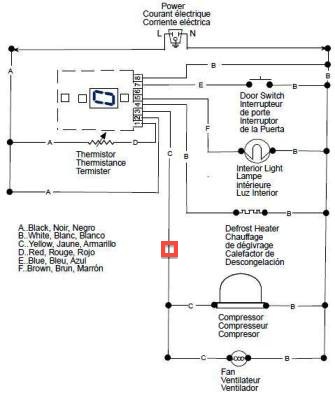
I am almost finished building the BrewTroller control box for the freezers. I am having a hard time figuring out the wiring for the freezers. I have the wiring diagram for the freezer here, and its clear that if I splice a relay into the yellow wire then I can control the compressor and fan internally. The problem is, how do I get 120v inside the freezer, how do I get the 12v+ and ground inside the freezer to control the 120v outlet, and how do I get the 3 wires needed for the temp sensor inside?
When Deep Six did his he had the controller inside the freezer which meant that everything he needed was already inside and nothing new needed to be connected externally. He also said he was able to find an internal constant on 120v line, I was not able to find this wire while testing.
The bundles of wires are set in pretty well and I dont think I can sneak any new wires into the freezer via existing pathways. The only opening I can see is via the drain at the bottom of the freezer. I dont know that this is the best choice to run 120v wires and the temp sensor wires into but it is looking like the only option.
Here is a picture of the wiring diagram from the freezer, in red I have indicated where I plan on installing the relay to control the compressor.
If anyone has any ideas on how to get the temp sensor wires inside or how to wire the outlet internally I would love to know. I already have the outlets installed in the panels and everything ready to wire up.
We have very similar Kenmore standing freezers to what deep six did here.
https://www.homebrewtalk.com/f51/my-new-fermentation-cabinets-66926/
However, we have a digital controller on our model and it appears the wiring is slightly different. Let me tell you what we are trying to do and hopefully we can figure out how to do it.
We are trying to make a heated and cooled fermentation chamber, being in upstate NY and needing to do both year round. The cooling is obvious, and we havent decided on the heating method yet, except we will simply have a relay controlled 120v outlet to which we can plug in a heating fan or wrap later.
Ideally the second of two outlets inside the freezer would be constantly on incase we wanted to add something else inside the freezer.
We have two freezers right now, and both are going to be controlled via a BrewTroller control board. We will have one 3-wire connector containing 12v+, 12+, and ground for 12v. One 12v wire will control the compressor for cooling, the other will control the 120v outlet for the heating device. We also will need an internal connection for the temperature probe. This requires a cable with 3 wires.
So the end result of modifying these freezers will be overriding the compressor so that a 12v signal operates the compressor and a second 12v signal enables the internal 120v outlet. Both of these wires are in the same 3pin MIC connector on the rear of the freezer. A standard CAT-5 connector on the rear connects the internal temperature probe to the external BrewTroller box. Inside, the freezer has an internal connector to easily disconnect the temperature probe.
I am almost finished building the BrewTroller control box for the freezers. I am having a hard time figuring out the wiring for the freezers. I have the wiring diagram for the freezer here, and its clear that if I splice a relay into the yellow wire then I can control the compressor and fan internally. The problem is, how do I get 120v inside the freezer, how do I get the 12v+ and ground inside the freezer to control the 120v outlet, and how do I get the 3 wires needed for the temp sensor inside?
When Deep Six did his he had the controller inside the freezer which meant that everything he needed was already inside and nothing new needed to be connected externally. He also said he was able to find an internal constant on 120v line, I was not able to find this wire while testing.
The bundles of wires are set in pretty well and I dont think I can sneak any new wires into the freezer via existing pathways. The only opening I can see is via the drain at the bottom of the freezer. I dont know that this is the best choice to run 120v wires and the temp sensor wires into but it is looking like the only option.
Here is a picture of the wiring diagram from the freezer, in red I have indicated where I plan on installing the relay to control the compressor.
If anyone has any ideas on how to get the temp sensor wires inside or how to wire the outlet internally I would love to know. I already have the outlets installed in the panels and everything ready to wire up.


