You are using an out of date browser. It may not display this or other websites correctly.
You should upgrade or use an alternative browser.
You should upgrade or use an alternative browser.
ebay aquarium temp controller build
- Thread starter android
- Start date

Help Support Homebrew Talk - Beer, Wine, Mead, & Cider Brewing Discussion Forum:
This site may earn a commission from merchant affiliate
links, including eBay, Amazon, and others.
Ummm. Look at the pictures. Carry the controller with you and know that you need an outlet and stuff. Plastic. Not a big deal. Maybe a cheap plastic toolbox with a handle? Wife's tupperware? (just kidding. Baaaad idea). I want to put the shiny lights on it too so that when ON I know it. Just because I can!
I haven't decided. I would love to mod something cool into a temperature controller though. Ah. I have a Mr. Beer type keg I don't want... Maybe that. Too bulky, though. Maybe a Simpson's "Beer, Ummm" lunchbox?
Any ideas? What says "Beer", is plastic, and would be a cool housing for temp controller and outlet?
Raymond
Mad_Milo
Well-Known Member
- Joined
- Mar 15, 2009
- Messages
- 209
- Reaction score
- 8
Are people putting the extra status lights on simply for the bling factor and because they can? The controller itself does have heat and cool status LEDs that light when the circuit is activated.
Just curious, that's all.
Just curious, that's all.
Mad_Milo said:Are people putting the extra status lights on simply for the bling factor and because they can? The controller itself does have heat and cool status LEDs that light when the circuit is activated.
Just curious, that's all.
A big red or blue light is easier to read than the teeny tiny red dot on the controller. Plus you can tell from across the room what it's doing
-= Jason =-
OP
OP
android
Well-Known Member
Are people putting the extra status lights on simply for the bling factor and because they can? The controller itself does have heat and cool status LEDs that light when the circuit is activated.
Just curious, that's all.
absolutely. i'm getting ready to build a second one and am blinging it out simply because i can. and i figure it's a way for me to learn a little more about electronics/wiring. i'm installing a rocker switch for main power and some lamps for heating and cooling as others have done.
agezzi
Well-Known Member
So I got to ask. Do u wire the fan straight in or do u still need a ac adapter hooked to the fan and then plugged into the relay? As in wire a plug to the relay and then plug the adapter into the plug. Any help would b great
Mad_Milo
Well-Known Member
- Joined
- Mar 15, 2009
- Messages
- 209
- Reaction score
- 8
So I got to ask. Do u wire the fan straight in or do u still need a ac adapter hooked to the fan and then plugged into the relay? As in wire a plug to the relay and then plug the adapter into the plug. Any help would b great
Depends on the fan.
 Most fans scavenged from computers are 12VDC and need an adapter. There are 120VAC fans out there, but not very common in the small scale.
I have mine wired to a DC adapter, and it runs continuously to keep the temps as even as possible.
agezzi
Well-Known Member
Mad_Milo said:Depends on the fan.
I have mine wired to a DC adapter, and it runs continuously to keep the temps as even as possible.
Ok I wrote that wrong. So I need to hard wire on a female plug from the relay then plug my 12v adapter hooked up to the fan to that. Hope that's correct, I get the rest of the diagram it's just the part were the fan hooks up. Sry I'm having a brain fart
Thanks, for this great build post. I only have a very rudimentary knowledge of electricity and have run into a problem. All my connections are as shown in the original diagram, but as the freezers approaches the target temp it continues to run. the heat side turns on, but the freezer continues to chill well past the target temp. any ideas as to why this might be happening?
thanks,
tim
thanks,
tim
If you're positive that it's all wired correctly and it's behaving that way, then the relay that controls cooling is busted and stuck in the closed position.
It would be time to contact your seller for a refund or exchange.
Do you have a multimeter to do any testing with?
Does the fridge run even if the controller is turned off?
It would be time to contact your seller for a refund or exchange.
Do you have a multimeter to do any testing with?
Does the fridge run even if the controller is turned off?
ToastedPenguin
Well-Known Member
Its been about a year since this thread was started, can anyone provide feedback on how well the STC-1000 stacks up? Its priced about half that of a Love Controller and I am in the process of building a keezer out of a 14.8 cuft. freezer I just picked up so I'd be interested in knowing if this controller would work for my needs.
Thanks,
David
Thanks,
David
Mad_Milo
Well-Known Member
- Joined
- Mar 15, 2009
- Messages
- 209
- Reaction score
- 8
Double check that you don't have a few stray wires making the bridge. Do you hear a click when the temp hits the set point, and the cool circuit engages?
OP
OP
android
Well-Known Member
Its been about a year since this thread was started, can anyone provide feedback on how well the STC-1000 stacks up? Its priced about half that of a Love Controller and I am in the process of building a keezer out of a 14.8 cuft. freezer I just picked up so I'd be interested in knowing if this controller would work for my needs.
Thanks,
David
still chugging along like a champ. no problems at all so far with mine. i use it to control my keezer, so it's had power supplied to it damn near this whole time.
the freezer runs no matter what on the cold side. the heat side flips on a light when it hits the set temp. I figured it was something similar to what you said, thanks for confirming my suspicions.
Which suspicion? I think most replies, I did mine in a pm, were asking you to double check your wiring. If you have a multi-meter, there is a simple check you can do by removing a few wires from the controller. Without one, it requires wiring a test circuit almost as complex as the circuit you want to test. It would be very rare, but possible, to have a bad relay. The simplest answer does not point to the relay.
agezzi
Well-Known Member
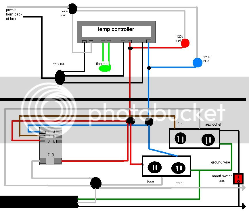
hey if someone would take a look at this and let me know if this will do it for me. all of it will be inside a project box....thanks for the help
edit: the black circles are all wire nuts
Salmonhouse
Well-Known Member
I just got all my parts for this, what did you guys use to cut the plastic? I'm not sure if i want to spring for a Dremel tool just yet.
agezzi
Well-Known Member
Salmonhouse said:I just got all my parts for this, what did you guys use to cut the plastic? I'm not sure if i want to spring for a Dremel tool just yet.
Dremel is the way to go. I also used a step bit to make the other holes.
I just got all my parts for this, what did you guys use to cut the plastic? I'm not sure if i want to spring for a Dremel tool just yet.
If you have a harbor freight near you(which living in Seattle you do), you can get a very cheap Dremmel knockoff. http://www.harborfreight.com/80-piece-rotary-tool-kit-97626.html
They may not last forever but hell, neither did my old dremmel.
F* using a dremel, it doesn't CUT the plastic it melts it thus causing you to spend more time cleaning up the edges.
I used a razor knife / box cuter / razor blade
what ever you want to call it. score you line several times, then you can puncture the plastic and cut your straight line.
done this on two boxes so. the dremel method I tried on my first box pissed me off. the razorblade just plain works.
-=jason=-
I used a razor knife / box cuter / razor blade
what ever you want to call it. score you line several times, then you can puncture the plastic and cut your straight line.
done this on two boxes so. the dremel method I tried on my first box pissed me off. the razorblade just plain works.
-=jason=-
For anyone who has mounted into a project enclosure, any special considerations that need to be taken in mounting the outlets in regards to making sure that they are sturdily mounted?
I am concerned that the first time I go to plug something in, that I will snap of the enclosure at the screw holes that I plan to mount through. Thought about a bead of epoxy to hold tight, but was curious to how others might have addressed this.
I am concerned that the first time I go to plug something in, that I will snap of the enclosure at the screw holes that I plan to mount through. Thought about a bead of epoxy to hold tight, but was curious to how others might have addressed this.
For anyone who has mounted into a project enclosure, any special considerations that need to be taken in mounting the outlets in regards to making sure that they are sturdily mounted?
I am concerned that the first time I go to plug something in, that I will snap of the enclosure at the screw holes that I plan to mount through. Thought about a bead of epoxy to hold tight, but was curious to how others might have addressed this.
You could mount a thin piece of steel or maybe even buy box extender from HD or Lowes to mount behind it so the mounting screws have something to go into.
http://www.homedepot.com/h_d1/N-5yc...splay?langId=-1&storeId=10051&catalogId=10053
or maybe even buy box extender from HD or Lowes to mount behind it so the mounting screws have something to go into.
http://www.homedepot.com/h_d1/N-5yc...splay?langId=-1&storeId=10051&catalogId=10053
That is a great idea. It should help distribute the load off of the actual screw holes themselves. Once the opening is cut, I could easily epoxy that to the enclosure and then be able to swap out the outlets should the need arise.
Cheers!

agezzi
Well-Known Member
agezzi said:hey if someone would take a look at this and let me know if this will do it for me. all of it will be inside a project box....thanks for the help
edit: the black circles are all wire nuts
Sorry to ask again but I'm eager to finish wiring this up and plugging her in. Can someone please look at the diagram and let me know if I'm good to go, or getting ready for a light show.
(it's like being a little kid at Christmas and mom forgot the batteries)
Edit: the pic didn't show up, its a few posts up from this one. Thanks again
Mad_Milo
Well-Known Member
- Joined
- Mar 15, 2009
- Messages
- 209
- Reaction score
- 8
hey if someone would take a look at this and let me know if this will do it for me. all of it will be inside a project box....thanks for the help
edit: the black circles are all wire nuts
The diagram is very confusing. It looks like you have neutrals attached at the relay points? Those should be black(hot) only.
agezzi
Well-Known Member
sry for the mess. the only neutral is attached to #7 on the relay.blue and red are hot. brown is the hot that goes to the fan outlet. grey is neutral. please commentThe diagram is very confusing. It looks like you have neutrals attached at the relay points? Those should be black(hot) only.
Mad_Milo
Well-Known Member
- Joined
- Mar 15, 2009
- Messages
- 209
- Reaction score
- 8
My mistake. I read the blue and red circles as wire nuts, not lights. I'm not familiar with the wiring block, but if the fan gets activated by the cool circuit will the power go to the heating circuit and turn that on?
I'm not an electrician by any means. Just another set of eyes.
I'm not an electrician by any means. Just another set of eyes.
sry for the mess. the only neutral is attached to #7 on the relay.blue and red are hot. brown is the hot that goes to the fan outlet. grey is neutral. please comment
This looks like a copy of a previous schematic for a controller with a relay for the fan output. If it is the same one, that one was vetted. If you based yours off of that, but changed something, it would be best to state what you changed. It seems correct, but is VERY dependent on the schematic/pin-out of the fan relay you choose to use, which is not stated.
agezzi
Well-Known Member
the grey block with 8 pins is the relay from radioshack(125v), and yes it is based off a prior schematic. i only added a extra hot for a aux outlet and a switch to turn off aux if needed. there r 2 outlets but both r split to make 4 outlets. heat/cold/fan/aux. im no electrician either i just want to make sure im not going to catch fire. as well this is going into one project box,unlike the other that was split into two diffrent boxes. Anything helps. if you see anything that would make an improvement dont hessitate to commentThis looks like a copy of a previous schematic for a controller with a relay for the fan output. If it is the same one, that one was vetted. If you based yours off of that, but changed something, it would be best to state what you changed. It seems correct, but is VERY dependent on the schematic/pin-out of the fan relay you choose to use, which is not stated.
here is a quick outline of my two plugs, switch and lamp light control unit. all done in a 7X5X3 box. quick and easy.

agezzi
Well-Known Member
theres no pic. anyway to pm me the pic,or re-post. your profile shows no pic,its just emptyhere is a quick outline of my two plugs, switch and lamp light control unit. all done in a 7X5X3 box. quick and easy.
Salmonhouse
Well-Known Member
OK, my build is done, i had to melt through the plastic by heating a razor with a propane torch, held it with some vice grips. I originally Tried to score it but after like 50 scores i realized it wasn't going to happen that way. Perhaps my project box was thicker than usual, i dunno.
A little late to the party, but did some test cuts in my enclosure to figure out what the best way is to cut square holes. What worked best for me was drilling out the corners and taking the coping saw to it. Also, an Xacto knife with one of the serrated blades works, as well - just much slower than the coping saw. Felt like I had more fine control with the Xacto knife, but not the patience to keep on using it, as it was much slower.
Both methods left clean cuts that only needed a light sanding.
Both methods left clean cuts that only needed a light sanding.
Salmonhouse
Well-Known Member
This temp controller is way cool! Got it hooked up temporarily, still need to build a 'chamber' out of my closet. But even in my bedroom it's Holding steady at 22-23C! I have the probe against one of the carboys:

I have the probe against one of the carboys:
mikeal
Well-Known Member
I like the custom ultraviolet radiation barriers!
Bjornbrewer
Well-Known Member
- Joined
- Jul 31, 2008
- Messages
- 417
- Reaction score
- 3
Is your beer really that ugly you need to paper bag it???
Salmonhouse
Well-Known Member
I thought you guys would like the brown paper bags. Watch now, it'll be a HBT trend!
Rememeber, REUSE is one of the 3 R's.
Rememeber, REUSE is one of the 3 R's.
OP
OP
android
Well-Known Member
here is a quick outline of my two plugs, switch and lamp light control unit. all done in a 7X5X3 box. quick and easy.
where did you find the 110v lamps? i could only find red and blue ones in 12v at radio shack.
where did you find the 110v lamps? i could only find red and blue ones in 12v at radio shack.
That's because Radio Shack sucks. I don't have lamps on my fridge controller, but I used 120V lamps on my HERMS control panel. They were like $1 each from mouser.com.
Shipping might get you on such a small order, though. I bought mine at the same time as I bought a ton of things for the system build.
Similar threads
- Replies
- 14
- Views
- 1K
