Wiring my PID, SSR and heat sink

Homebrew Talk - Beer, Wine, Mead, & Cider Brewing Discussion Forum

Help Support Homebrew Talk - Beer, Wine, Mead, & Cider Brewing Discussion Forum:

This site may earn a commission from merchant affiliate links, including eBay, Amazon, and others.

ILOVEBEER

Well-Known Member
Joined
Sep 4, 2009
Messages
716
Reaction score
6
Location
CA
Hello all,

I ordered a SYL-2352 PID controller, a 25A relay, a heatsink for the relay and the 1/4" NPT water tight temp probe from AUBERINS.com

I read the pamphlet that came with the relay and cannot make heads or tails of the wiring schematic. I dabble in 110V wiring and am mechanically sound in fabrication...but man I feel retarded reading this thing.

Does anyone have any tips or pics on how they put together this same set of components?

I have a two tier RIMS system I am building. The heater element is a 4500W 240V element that I will run @ 110V (1300-1500W) just to keep the mash at myset temperature as I sparge it using my pump. I talked to the guy at AUBERINS and he said it would be totally sufficient power and fulfill my needs.

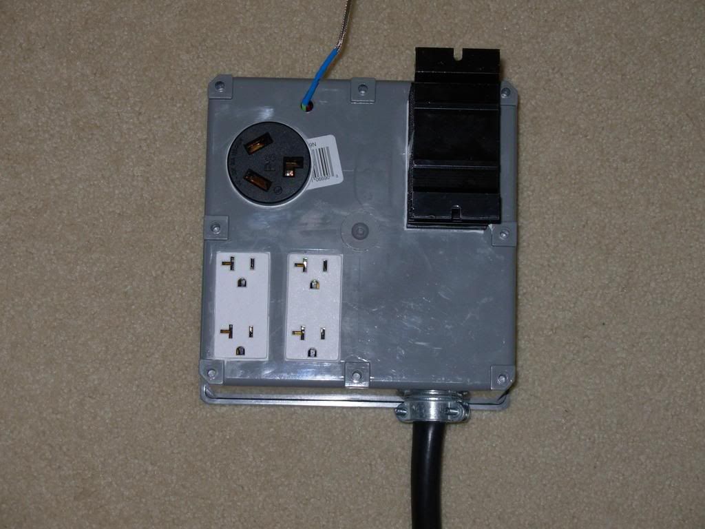
I bought a PVC underground junction box I plan to put it all into.

Any tips would be awesome.

Thanks
Joe
 
Just think of the relay as a light switch. The 2 smaller terminals (usually) are for the low voltage control from the PID, they send the signal to the switch (like your hand flicking the light switch on). The larger terminals are used to interrupt the hot power lead that goes to your element. The neutral and ground are wired as normal out of this loop. The temp probe goes to the PID and tells it when its time to send the signal to the relay.

I think I explained it correctly, should make sense when looking at the pamphlet. I am not an electrician but wired up all my stuff just by thinking about how it relates to a normal switch set up.
 
I kinda get it but I think all the talk of alarms and other items confused me. I will read a littlle further. Here is my plan:

I have a thick plastic junction box that will house everything. I have a heavy gauge extension cord I will use as my power source, I plan to utilize a 110V rated switch to power everything on and off.

Now from this point solid copper wiring goes from my switch to the #9 & #10 connections (labeled AC85 242V) on the PID?

On the PID labeled SSR + & - what type of wiring is used here, also soild copper?

I kind of understand.

Thanks

It's really very simple. I modified the pin numbers on my drawing in the "RIMS for Dummies" thread I told you about for you PID. Just wire it as it is shown. Use 22 awg wire (it doesn't matter stranded or not) for the 120 volt power to the PID and the wire from the PID to the SSR. Of course the wire from the element to the SSR AC side should be of sufficient size to handle the current draw of your element. If you are not sure please ask questions. We don't want you blowing any of the stuff you just bought up.

ILOVEBEER RIMS.jpg
 
Man you are awesome. I do have questions and please bare with me...I really want to make sure I am doing this correctly....

Numbers 9 & 10 on the PID are 115 VAC (your pic) I have plans to put in a household 115VAC switch that will get power from a heavy duty extension cord properly spliced into it, that will power numbers 9 & 10...allowing the system to be on a switch.

Numbers 4 & 5 are for the thermometer probe. I am looking at mine I purchased from Auberins (after talking to the tech and choosing all items on his advice)...it has 3 wires 2 red and 1 white....any ideas which get used and where the 3rd gets used if at all?

On the heating element side I was in total focus until I saw that on the output side of the SSR before the element you have the 115 VAC Neutral and Hot going to the right of the page???? I thought those went straight to the element one black one white. Could those go to a 110V receptacle to plug the pump into? Perhaps I am missing something.

Thank you so much for your help so far!
Joe
 
Hello.

I decided to include the part #'s that I purchased. I figure since you or someone is very familiar with the AUBERINS.com website they can tell me if the tech who guided me in my purchase gave me the correct advice...namely the temp sensor/thermocouple.

1 * heat sink 25A #HS25

1 * 1/16 DIN PID temp controller (SSR output) #SYL-2352

1 * 25A SSR #RS1A40D25

1 * Liquid tight RTD sensor 2" probe 1/4" NPT #PT100-L50NPT


If someone has a chance to look these up on the site and let me know if the thermocouple (the item in question since it has 3 wires not 2) is the correct one for my setup.


Thank you for your help.

Joe
 
Yah, that should work... it is an RTD, not a thermocouple, so you have three leads. There should be pins on the back of the PID that are specifically for this, this will be noted in the manual to the PID.
 
Awesome.

Hey Pol,

On the above schematic that SAWDUSTGUY shared with me, where do you think the 115 VAC hot and neutral wired between the SSR and heater element go that exit to the right of the page? Perhaps I don't understand 110 VAC schematics?

Thanks
 
Awesome.

Hey Pol,

On the above schematic that SAWDUSTGUY shared with me, where do you think the 115 VAC hot and neutral wired between the SSR and heater element go that exit to the right of the page? Perhaps I don't understand 110 VAC schematics?

Thanks

Well the HOT is COMING IN from the left side to the SSR. The NEAUTRAL is actually coming IN to the element... both from the 115VAC source that is feeding everything, typically a distribution block.
 
I am a retard!!!!! Sorry for all the stupid questions.

I called Auberins and ran through it with the tech (I was irritating him with my elementary questions). I finally got it.

He suggested I use a two pole switch...one at the 110 source coming in to power the PID and one to interrrupt the power on the "output" side of the SSR to the element for temperature only readings.
Does this sound ok?
 
Yes, that is a good idea... I did that in my system, so that the PID still reads temp even with the element OFF.
 
Do you suggest I put the switch on the "constant" hot side of the SSR or the Side going to the element that get power after the SSR switches on...or does it matter?
 
Do you suggest I put the switch on the "constant" hot side of the SSR or the Side going to the element that get power after the SSR switches on...or does it matter?

Doesnt matter really. I put mine on the way IN to the SSR, so that the SSR isnt switching current when the element is off, that would be wasteful and just cause more wear on the SSR.
 
Very good point. Thank you for all your help and thanks for putting up with my ding dong questions
 
On a side note...the temp sensor I bought is the RTD type which is a more accurate temp sensor...according to the guy.

I have a little ways to go before I am done with my RIMS sytem but an looking forward to it....THEN I HAVE TO LEARN HOW TO USE IT. Wish me luck!


Hey Pol....by the way. I watched your HERMS video. I saw that your system is 240V and it looks very nice and wel though out. I was wondering what your control box is made of?
and......
I also noticed your heat sink was hung outside the box...is your SSR also mounted to the outside of the box? If not how did you secure the relay inside the box without sandwiching the case between the two?

Hope I made sense.

Thanks again!
Joe

The control box is an all weather junction box that I bought at Lowes, nothing special.

The heat sink is mounted TO the box, over a HOLE that is the same size as the SSR. Thusly, the heat sink it mounted to the box, the SSR is mounted to the heatsink. This allows the electronics to stay inside, but the heat sink to remain outside where it will properly cool the SSR.

EDIT: Here is the back
DSCN0987-1.jpg
 
Very nice job!

It looks like we purchased the same box (mine might be a little smaller 8x8x5).

I might have some trouble doing the same with the SSR and heat sink. The dimensions of my SSR and heat sink are identical lengthwise with the width dimensions of the heat sink being 1/8" bigger on each side at most. Hmmmmm....... I wonder how I can do this?

Do you think I could cut the hole small enough so the heat sink does NOT rest directly on the heat sink but also not fall through the junction box....space that gap with a good heat conductor like copper sheets cut to the same dimension of the bottom of the SSR and screw it together that way? Do you think it would work and still transfer heat to the heatsink properly?

Thanks
 
Man... I dunno. What I will say is that my heat sink barely gets warm to the touch.

You will want to make sure you have a great heat conductor in there, your heat sink came with heat grease right?
 
Yes it did...I knew I should have bought the 40AMP heat sink which has bigger dimensions. I'll figure something out....I will make small brackets that mount to the bottom of the heat sink that will push it up against the outside of the box...I think I will be ok...

Hey buddy thank you for taking the time to help me with this...I really appreciate it!!!!

Joe

No problem...
 
Will this PID (AGPtek® Dual Digital F/C PID Temperature Control Controller TA4-SSR With 2 Alarms) work with this SSr (uxcell
SSR-25 DA 25A 3-32V DC / 24-380V AC)it will also be wired at 110v with a 1500 W element I haven't found a lot of information about this PID so I am trying to reach out
 
Back
Top