You are using an out of date browser. It may not display this or other websites correctly.
You should upgrade or use an alternative browser.
You should upgrade or use an alternative browser.
Stc-1000+
- Thread starter alphaomega
- Start date

Help Support Homebrew Talk - Beer, Wine, Mead, & Cider Brewing Discussion Forum:
This site may earn a commission from merchant affiliate
links, including eBay, Amazon, and others.
Seriously did I just read this post right and you updated the STC1000+ project into a controller w/PID functionality? I'm not versed in this stuff but did flash to controllers nearly 2yrs ago now and followed Mats files quite easily. But now PID? Sorry for not reading the updates on the project, on vacation in Antigua!, but will when I return. Looking forward to it!!I made several updates to the README, User-Manual and the source-files. Software works fine, I did a few rounds of testing. I need to do some more testing with the PID controller, but it all seems to work. If you set parameter Ts (new) to a non-zero value (e.g. 20 seconds), you get PID-control instead of thermostat (on-off) control.
I replaced the stock microcontroller on a couple of devices with one that has more eeprom size. Description on how to do this is given in the README file. This works without problems and then you have Mats his version with 6 profiles and up to 9 temperature-time pairs again.
DodgeeDoo
Member
n/m I got it!! Thank you for the guides!
Last edited:
I am now having trouble uploading the sketch using the Arduino IDE.
It worked before but now it is just not working. Tried 3 different boards. 1x Uno, 1x cheap uno knock off and 1x cheap nano.
The nano was my dedicated flasher. It still works because it wants to still flash STC 1000+ version which is on it. Now I need to put a different version on an STC 1000 it just won't upload any sketch.
I'm using 1.6.10 on this machine.
stbernts
Well-Known Member
- Joined
- May 20, 2016
- Messages
- 257
- Reaction score
- 43
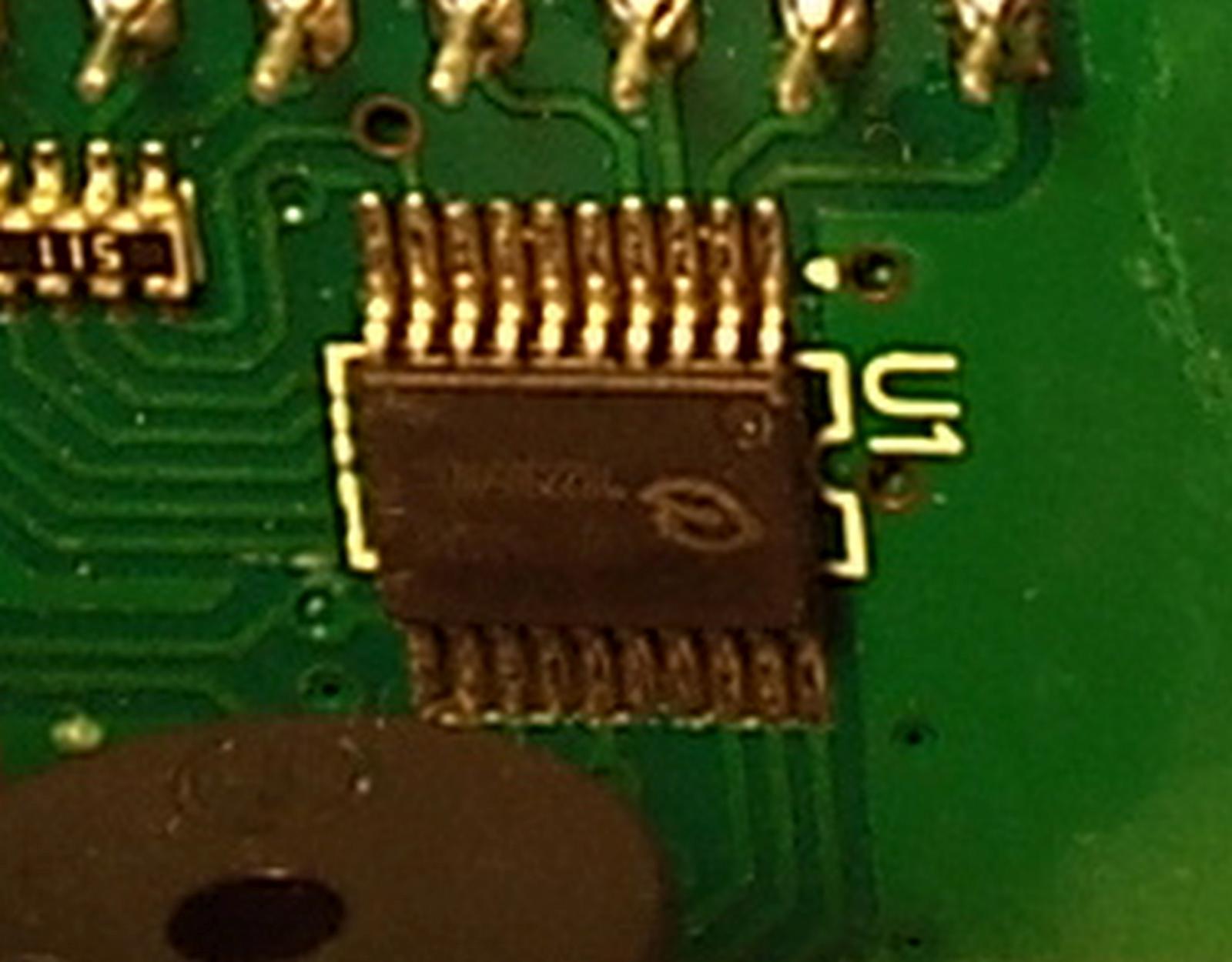
The code on top says '0602 05 R QC', the text on the frontpanel PCB says 'WR-032' and the text on the IC says '8S003F3P6'.
It would be nice if more people can confirm that the '0602 05 R QC' label is indeed a unique identifier for this particular hardware version. Makes ordering on ebay / Aliexpress less of a guess.
Will test this weekend
The code on top says '0602 05 R QC', the text on the frontpanel PCB says 'WR-032' and the text on the IC says '8S003F3P6'.
It would be nice if more people can confirm that the '0602 05 R QC' label is indeed a unique identifier for this particular hardware version. Makes ordering on ebay / Aliexpress less of a guess.
I can report that older units marked '0602 05 R QC' do not have this board version. I have 3 that are 2-3 years old and have board Power_v1.1 with chip N79A8211. Damn the bad luck.
Caveat: This is my first attempt at using STC-1000+ firmware, so I may have missed something.
Background of use of stock STC:
I have an electric brew-in-bag style system (basically an electric urn) - I have the stock firmware STC installed like this:
This allows the STC to turn the urn on / off during the mash to maintain temps. Aside from the above I have a march pump that I power up/down manually for recirculation.
STC1000+ Use case:
My plan is to use one of the new STC, with 1000p firmware in the exact same position as the above STC - however to be able to set a mash profile.
To do this I loaded the STC1000p sketch for OVBSC (https://github.com/matsstaff/stc1000p/tree/master/ovbsc) - the Celsius version.
I was rather overwhelmed by all the parameters that can be set for my simple use case (i.e mash step profiles) - but I set the following (leaving the reset to defaults):
- St (Stike water setpoint) - 70.5 deg
- Pt1 - 67 deg
- Pd1 - 70 mins
- Pt2 - 75.6 deg
- Pd2 - 20 mins
This was to align to my common simple mash profile of adding room temperature grains into 70.5 deg water, which then cools it to 67 deg which I hold for 70 mins (saccharification), then increase temp to 75.6 deg and hold for 20 mins (mash out)
Issue:
When I go to execute 'run' on the ST1000p enabled controller:
'Pr' run mode - switches the cooling relay on and off every 4 seconds
'Co' run mode - switches the heating relay on and off about every 4 seconds
Not certain if this is an issue? or if I'm missing some parameters to be set?
Background of use of stock STC:
I have an electric brew-in-bag style system (basically an electric urn) - I have the stock firmware STC installed like this:
Wall outlet -> stock STC (/w heating relay wired to another electric outlet) -> electric urn (with manual thermostat contstantly set to max).
This allows the STC to turn the urn on / off during the mash to maintain temps. Aside from the above I have a march pump that I power up/down manually for recirculation.
STC1000+ Use case:
My plan is to use one of the new STC, with 1000p firmware in the exact same position as the above STC - however to be able to set a mash profile.
To do this I loaded the STC1000p sketch for OVBSC (https://github.com/matsstaff/stc1000p/tree/master/ovbsc) - the Celsius version.
I was rather overwhelmed by all the parameters that can be set for my simple use case (i.e mash step profiles) - but I set the following (leaving the reset to defaults):
- St (Stike water setpoint) - 70.5 deg
- Pt1 - 67 deg
- Pd1 - 70 mins
- Pt2 - 75.6 deg
- Pd2 - 20 mins
This was to align to my common simple mash profile of adding room temperature grains into 70.5 deg water, which then cools it to 67 deg which I hold for 70 mins (saccharification), then increase temp to 75.6 deg and hold for 20 mins (mash out)
Issue:
When I go to execute 'run' on the ST1000p enabled controller:
'Pr' run mode - switches the cooling relay on and off every 4 seconds
'Co' run mode - switches the heating relay on and off about every 4 seconds
Not certain if this is an issue? or if I'm missing some parameters to be set?
I did a firmware flash on my first stc1000 to + a while ago, ut today when trying a second stc1000+ flash on another unit nothing happen. Hit "d" in seriel monitor but nothing happens exept arduino prog on my mac freezes and need to be restarted to work. It's Driving me crazy. What is wrong? Please!
Answering my own question:Caveat: This is my first attempt at using STC-1000+ firmware, so I may have missed something.
Background of use of stock STC:
I have an electric brew-in-bag style system (basically an electric urn) - I have the stock firmware STC installed like this:
This allows the STC to turn the urn on / off during the mash to maintain temps. Aside from the above I have a march pump that I power up/down manually for recirculation.
STC1000+ Use case:
My plan is to use one of the new STC, with 1000p firmware in the exact same position as the above STC - however to be able to set a mash profile.
To do this I loaded the STC1000p sketch for OVBSC (https://github.com/matsstaff/stc1000p/tree/master/ovbsc) - the Celsius version.
I was rather overwhelmed by all the parameters that can be set for my simple use case (i.e mash step profiles) - but I set the following (leaving the reset to defaults):
- St (Stike water setpoint) - 70.5 deg
- Pt1 - 67 deg
- Pd1 - 70 mins
- Pt2 - 75.6 deg
- Pd2 - 20 mins
This was to align to my common simple mash profile of adding room temperature grains into 70.5 deg water, which then cools it to 67 deg which I hold for 70 mins (saccharification), then increase temp to 75.6 deg and hold for 20 mins (mash out)
Issue:
When I go to execute 'run' on the ST1000p enabled controller:
'Pr' run mode - switches the cooling relay on and off every 4 seconds
'Co' run mode - switches the heating relay on and off about every 4 seconds
Not certain if this is an issue? or if I'm missing some parameters to be set?
'Pr' run mode - switches the cooling relay on and off every 4 seconds
This was due to the SO (Strike output) being set to >100% hence it was switching (PWM) the 'cooling' relay.
'Co' run mode - switches the heating relay on and off about every 4 seconds
This was due to the cO (Manual mode output) being set to <100% hence it was switching (PWM) the 'heating' relay
Last edited:
Hi Again - I've made some good progress with STC-1000+ and now have it routinely running my brew days, and have recently swapped out the mechanical relays for SSRs.
The next item I've been tackling is the Pump control via the unused pad on the STC to an SSR for use with an AC pump. I've gone over the old STC 1000+ PI thread and this one and seems many have doubts/concerns on the procedure...
I've read the directions here which states: "Connect the positive input of the SSR to the pin on the STC and add a pullup resistor (220-470 ohm) to +5v (you can find that on the programming header on the STC). Connect the negative input on the SSR to ground (can also be found on the STC programming header). "
The above refers to the programming header, which is annotated here
Then I've also looked at this post and specifically this image where the author captioned it with "This is the cable with the resistor, etc for the pump controller:"
This is what I take from this:
1. Install one wire from SSR (+) to unused pad (below and to the right of the J2 label)
2. Install one wire from STC Programming header +5V with a 220-470 ohm resistor inline to the SSR (+)
3. Install one wire from SSR (-) to STC Programming header Ground/GND
Some questions and doubts:
1. In the completed cable above it appears to be 'sharing' the programming lead (which I like) - however I see All 3 wires coming from the programming header? How is that possible if the instructions state to use the unused pad to SSR (+)?
2. Can anyone point me to some guidance on how best to put the resistor inline?
Photos / Diagrams would be great!
Hi Again - I've made some good progress with STC-1000+ and now have it routinely running my brew days, and have recently swapped out the mechanical relays for SSRs.
The next item I've been tackling is the Pump control via the unused pad on the STC to an SSR for use with an AC pump. I've gone over the old STC 1000+ PI thread and this one and seems many have doubts/concerns on the procedure...
I've read the directions here which states: "Connect the positive input of the SSR to the pin on the STC and add a pullup resistor (220-470 ohm) to +5v (you can find that on the programming header on the STC). Connect the negative input on the SSR to ground (can also be found on the STC programming header). "
The above refers to the programming header, which is annotated here
Then I've also looked at this post and specifically this image where the author captioned it with "This is the cable with the resistor, etc for the pump controller:"
This is what I take from this:
1. Install one wire from SSR (+) to unused pad (below and to the right of the J2 label)
2. Install one wire from STC Programming header +5V with a 220-470 ohm resistor inline to the SSR (+)
3. Install one wire from SSR (-) to STC Programming header Ground/GND
Some questions and doubts:
1. In the completed cable above it appears to be 'sharing' the programming lead (which I like) - however I see All 3 wires coming from the programming header? How is that possible if the instructions state to use the unused pad to SSR (+)?
2. Can anyone point me to some guidance on how best to put the resistor inline?
Photos / Diagrams would be great!
Answering my own question:
A physical representation of my wiring:
STC (5v header) -----------Resistor----|---------> SSR (+)
STC (Unused Pad)-----------------------|
STC (Ground header) -----------------------------> SSR (-)
In my case I needed to use a 220ohm pull up resistor, as the 470ohm was only giving 2.3V hence not enought to switch the SSR.
FireManDan
Well-Known Member
- Joined
- Oct 11, 2013
- Messages
- 85
- Reaction score
- 21
Good Morning, for that last week have been doing online searches and research on the STC1000's. I learned of the awesome flashing of the units to turn them into the 1000+. I am a DIY'er and I really want to build and flash my own fermentation controller. With all that said I have been searching for an STC with the proper hardware revision. I have had no luck, can anyone point me in the right direction for an updated supplier of STC1000 with the proper hardware so that I would be able to flash? Any advice would be greatly appreciated.
Cheers!
Cheers!
alphaomega
Well-Known Member
- Joined
- Jul 10, 2013
- Messages
- 1,041
- Reaction score
- 461
@FireManDan:
This should be the right one (but AliExpress has been known to send the wrong type anyway):
https://www.aliexpress.com/store/product/temperature-controller-STC-1000/1305777_2004466302.html
Otherwise, chances are you'll get an STM8 based unit and can give Emile's version a try
This should be the right one (but AliExpress has been known to send the wrong type anyway):
https://www.aliexpress.com/store/product/temperature-controller-STC-1000/1305777_2004466302.html
Otherwise, chances are you'll get an STM8 based unit and can give Emile's version a try
FireManDan
Well-Known Member
- Joined
- Oct 11, 2013
- Messages
- 85
- Reaction score
- 21
@FireManDan:
This should be the right one (but AliExpress has been known to send the wrong type anyway):
https://www.aliexpress.com/store/product/temperature-controller-STC-1000/1305777_2004466302.html
Otherwise, chances are you'll get an STM8 based unit and can give Emile's version a try
Thank you very much I will buy a couple of these and then move on to the STM8 if need be.
yes I now have 3 controllers bought from there. none are the right thing and don't look like Emile's one ether. they may be stm8's but figuring out where to input the data..... so I ended up building an "Ardbir" instead (uno based) now I have a screen thats in english and buttons my fat fingers can work.
don't get me wrong. I respect all the hard work thats gone into this project. maybe its the 230 volt thing but I just can't get supplied with the correct Stc1000. on the upside my brews have never been better
don't get me wrong. I respect all the hard work thats gone into this project. maybe its the 230 volt thing but I just can't get supplied with the correct Stc1000. on the upside my brews have never been better
FireManDan
Well-Known Member
- Joined
- Oct 11, 2013
- Messages
- 85
- Reaction score
- 21
Well Crap. So worst case it'll be in Celsius and I will have to manually adjust my temperature according to my fermentation schedule? Do you have any links to the plans for the fermentation controller that you built?
alphaomega
Well-Known Member
- Joined
- Jul 10, 2013
- Messages
- 1,041
- Reaction score
- 461
@Arctic & @FireManDan: Well, there are a number of ppl that have got the right controller from there also. And it specifically lists A400_P, so if you don't get one, from what I heard, Ali is quite reasonable in making up for that.
FireManDan
Well-Known Member
- Joined
- Oct 11, 2013
- Messages
- 85
- Reaction score
- 21
@alphaomega you are absolutely right. I recall seeing that in the description. I'm just going to pull the trigger and patiently wait. Thanks again for everyone's input and advice.
I did complain about the units they sent me, but as they DO exactly what was advertised (even if not the right thing for 1000+) there was nothing I could do.

On the upside really happy with MY end result.
see https://www.homebrewtalk.com/showthread.php?t=540002
the Op of this thread has now gotten greedy and is selling a chinese made version which looks like the stc1000
but the files are still available on the net will stick em on my own site soon to make sure of it.

Bigdaddyale
Well-Known Member
I would look at https://www.homebrewtalk.com/showthread.php?t=569497 before ArdBid.
Terragady made a pcb for both systems. I have extra v4.2 boards available for CraftBeerPi. With all of that said I still use my STC100+ units because they are easy to use once you set them up. not depended on wifi.
Terragady made a pcb for both systems. I have extra v4.2 boards available for CraftBeerPi. With all of that said I still use my STC100+ units because they are easy to use once you set them up. not depended on wifi.
alphaomega
Well-Known Member
- Joined
- Jul 10, 2013
- Messages
- 1,041
- Reaction score
- 461
I did complain about the units they sent me, but as they DO exactly what was advertised (even if not the right thing for 1000+) there was nothing I could do.
Well, if you got them from that specific Ali store, then they're not as advertised, as it specifically states A400_P. I've heard others have gotten refunds after being sent wrong type units.
There's the inkbird thermostats as well. So, I guess there are a lot of options, depending on what your needs/wants are.
Edit: Personally though, CraftBeerPi has got licensing issues and last time I looked at the ArdBir code (which admittedly was quite some time ago), it was a royal mess.
I'm certainly biased, but the STC is good enough for my needs, so I think I'll stick to that
... CraftBeerPi has got licensing issues ...
 Can you summarize the CraftBeerPi licensing issues, or provide a link with information?
Brew on

alphaomega
Well-Known Member
- Joined
- Jul 10, 2013
- Messages
- 1,041
- Reaction score
- 461
You can just read the license here:
https://github.com/Manuel83/craftbeerpi/blob/master/LICENSE
https://github.com/Manuel83/craftbeerpi/blob/master/LICENSE
yes I now have 3 controllers bought from there. none are the right thing and don't look like Emile's one ether. they may be stm8's but figuring out where to input the data.....
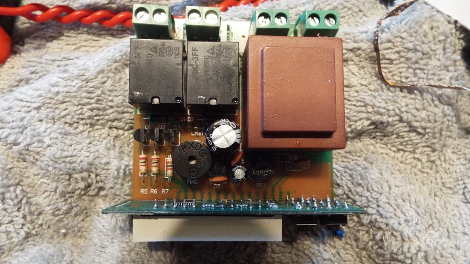
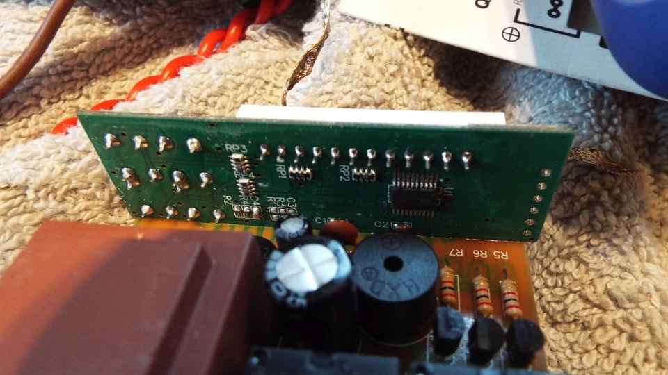
Arctic, can you send or publish some pictures of the internal PCBs? I ordered various STC-1000 and they all had the same hardware (STM8 microcontroller). Interesting to see what you received.
Thanks for the pictures! This chip is a chinese 8051 clone and is not an stm8 nor a PIC microcontroller. I have an identical version and got it by following the link Mats gave for a PIC version. So the PIC versions are probably no longer available.
This clone only has chinese documentation, so I gave up trying to identify if and how this thing is programmable.
If you order on ebay, you probable get the v2 hardware of the STM8 (see https://github.com/Emile666/stc1000_stm8/blob/master/WR-032-v2-2016-4-7.md). But you only know for sure when they are delivered. I ordered a few on them on ebay (http://www.ebay.com/itm/Digital-STC...With-Sensor-New-/131951655891?var=&hash=item0), so maybe you have luck with getting the STM8 v2.
As an alternative however: I am busy creating new versions of both PCBs (frontend and backplane), so you have all the STM8 option available again (with wireless nRF24L01 control and One-Wire sensor interface). Most of the components on this PCB can be reused if you are willing to do some de/resoldering. But it is still work in progress.
alphaomega
Well-Known Member
- Joined
- Jul 10, 2013
- Messages
- 1,041
- Reaction score
- 461
Thanks for the pictures! This chip is a chinese 8051 clone and is not an stm8 nor a PIC microcontroller. I have an identical version and got it by following the link Mats gave for a PIC version. So the PIC versions are probably no longer available.
I do think they are still available. Ordering straight from the manufacturer, you'd definitely get the right one (but they will only sell in bulk). The manufacturer uses AliExpress to sell their products in lower quantities, but I think the ethics of AliExpress is quite... relaxed... so, they'll just send anything anyways... There are a lot of ppl though that have got the right units form there as well. But it sucks that you can't be sure...
But I agree, as clones are becoming cheaper, finding the PIC units (from anywhere other than the manufacturer) is probably only gonna get harder (that's what she said).
Emile666 said:This clone only has chinese documentation, so I gave up trying to identify if and how this thing is programmable.
I've had a look as well at a few of the other clones, and had the same conclusion. None of them seem 'open' enough to do anything about (i.e. lacking in documentation and/or tools).
Emile666 said:If you order on ebay, you probable get the v2 hardware of the STM8 (see https://github.com/Emile666/stc1000_stm8/blob/master/WR-032-v2-2016-4-7.md). But you only know for sure when they are delivered. I ordered a few on them on ebay (http://www.ebay.com/itm/Digital-STC...With-Sensor-New-/131951655891?var=&hash=item0), so maybe you have luck with getting the STM8 v2.
As an alternative however: I am busy creating new versions of both PCBs (frontend and backplane), so you have all the STM8 option available again (with wireless nRF24L01 control and One-Wire sensor interface). Most of the components on this PCB can be reused if you are willing to do some de/resoldering. But it is still work in progress.
One can only hope that the STM8 ones become the most common one, as the PIC ones are getting harder to find, but it is always nice with alternatives and more features is always cool, wireless communication is certainly welcome
Cheers!
alphaomega
Well-Known Member
- Joined
- Jul 10, 2013
- Messages
- 1,041
- Reaction score
- 461
@gillie: Yes, you add them together
PF
1 Pump during heating of strike water
2 Pump during ramping up to reach next mash steps
4 Pump during the mash steps
8 Pump during heating up to reach hot break
16 Pump during hot break
So, if you want the pump to run during heating of strike water, ramping up to reach next mash steps and during the mash steps, you'd set PF to 1+2+4 = 7.
Cheers!
alphaomega
Well-Known Member
- Joined
- Jul 10, 2013
- Messages
- 1,041
- Reaction score
- 461
@gillie: No, not really. Currently, the program ends when boil time is up. After that you're on your own 
You can however manually turn on the pump by setting the cP parameter to 1 and then turn it off (cP = 0) after you're done whirlpooling.
You can however manually turn on the pump by setting the cP parameter to 1 and then turn it off (cP = 0) after you're done whirlpooling.
gillie
Member
- Joined
- Apr 18, 2012
- Messages
- 22
- Reaction score
- 0
Ok I changed the APF numbers from the preset and now the alarms are not working ? in test #1 there was alarms for the dough in etc now nothing ? Not sure but would using a incorrect number do this, it still functioned correctly just no alarms?
alphaomega
Well-Known Member
- Joined
- Jul 10, 2013
- Messages
- 1,041
- Reaction score
- 461
Yes it would. The APF toggles alarms and pauses.
I suggest you read the documentation. I've tried to explain it as best I could there.
I suggest you read the documentation. I've tried to explain it as best I could there.
Similar threads
- Replies
- 0
- Views
- 583
- Replies
- 2
- Views
- 901
- Replies
- 0
- Views
- 725

