Simple SSVR-controlled e-BIAB rig

Homebrew Talk - Beer, Wine, Mead, & Cider Brewing Discussion Forum

Help Support Homebrew Talk - Beer, Wine, Mead, & Cider Brewing Discussion Forum:

This site may earn a commission from merchant affiliate links, including eBay, Amazon, and others.
wottaguy....could you PM me please. I am going to go home and start going through this whole thing again to make sure I don't fry another switch or meter. I'm kind of confused and hope that pogden would chime in soon to elaborate as to why his build seems to be so different from mine, despite the fact that I'm using the EXACT same parts that he listed in his parts list. I can only assume he is using a 240V contactor, and that he is getting away with having only leg go to the switch because 120V theoretically should not make the contactor close. I'm not completely convinced I shorted the switch, as my fuse is still good following the incident, but I will run a continuity test on it tonight.

I used a 4-wire dryer cord too, and wire capped the neutral wire. My two hot leads went to the contactor main lugs on the input side. From there my red hot lead goes to the fuse and then 13 on the switch. Then 23 and 24 and tied together, and 23 also goes to the coil side of the contactor. the black hot lead on the contacor goes directly to the coil side....any thoughts....ANYONE!?!?
 
So I checked the continuity across major test points on the contactor and the switch and quickly found that my 13 to 14 contact on the switch was remaining closed despite the button being depressed and then pressed again. I could actually see that the contact inside the switch was not moving properly, so i moved my wiring over to the 23 and 24 side of the switch, and now everything is working properly. Just like pogden noted in his OP, since the contactor has a 240v coil, I believe that by switching only one hot leg, the contactor will open the circuit when there is only one hot leg attached to the coil and energized. I powered up the system last night, and the meter worked, and the switch worked correctly as well, so all is right with the world. I followed pogdens wiring schematic to a "T", so apparently there is more than one way to wire this system up correctly and get the same results. Here is my panel powered up and thankfully, not smoking any PCBs this time. Thanks again for the help everyone!

IMG_2666.jpg
 
Congrats...glad you found the issue and corrected it. I'll be doing some more testing and calibration today...BTW...I added another switch and circuit for my pump and all is good with that too. Now...Let's Brew..!!

tryoutpnl01.jpg
 
Congrats...glad you found the issue and corrected it. I'll be doing some more testing and calibration today...BTW...I added another switch and circuit for my pump and all is good with that too. Now...Let's Brew..!!


Did you just take the neutral from your dryer cord and one of the hot leads to break out 120V for your pump then?
 
Did you just take the neutral from your dryer cord and one of the hot leads to break out 120V for your pump then?

Yes..that is what I did. Added 2 terminal strips inside the box, the spst switch to the cover and wired the switch with one hot lead from the input side of the contactor to one terminal strip, and the other to the neutral terminal strip. That way I don't have to have the element or even the push button switch activated to run the pump. As long as the box's main power is plugged in and alive I am able to run the pump.
 
I'd like to send out a BIG THANKS to pogden for his design and this post. I had fun with this build and it was very cost effective compared to other builds I've seen and built. It works great and so far I am very happy with the results.
 
Absolutely...thanks pogden! I think I will stick with my remote control idea for my pump, but I do like your idea as well wottaguy.


Sent from my iPhone using Home Brew
 
Gents,

Sorry I've been silent for a bit - I was actually on vacation in the Scotland (drinking single malt), England (trying many of the surprisingly large variety of craft brews available), and Ireland (you guessed it - nothing but Guinness, and lots of it).

I'm glad you guys found my build helpful - HBT has been inspirational and informative, so I'm happy to be able to "give back" in any way I can.

Wottaguy's wiring approach is pretty much exactly like what's depicted in the Auber documentation. My approach was (in my mind, anyway) a little simpler, with fewer connections to be made (and potentially cause problems). For example, there's no real need to run both legs of the 240 through the switch - you just need to energize/de-engergize the contactor's coil, and that can be done by making/breaking the circuit on one leg, with the other leg wired directly to the coil.

Wottaguy said:
The way I viewed pogden's version of the switch wiring is that it looked to me that if running a 240v circuit if would fry the switch...

I don't quite understand this, but I'm certain that the switch won't fry if wired up exactly as I've shown - the only load on the switch is the contactor's coil, the LED, and the meter, and together they can't be drawing anywhere near 10A. I think it's more likely that Lapper just got a defective part from Auber. Or, maybe even more likely - you got a defective meter that somehow drew more than 10A? Lapper - did you end up buying another volt/amp meter?
 
Pogden,

Not sure how much of the thread you were able to read back on yet, but yeah, I had a spare meter (bought two in case this happened) so I wired it up correctly this time and it works fine. As others have pointed out, the connections for the AC input and the transformer input has had a couple variations (with regard to which connector actually applied to the aforementioned inputs), so when I was wiring my meter up, I just did it exactly like you did it, not paying attention to the fact that the molex connector was actually for the CT input, and NOT NOT NOT, I repeat NOT the AC input....HAHA. That meter didn't last longer than a blink of the eye and it was fried when I closed the circuit the first time.The switch on the other hand was in fact faulty, and when I e-mailed Auber about it, their product support guy basically just sent me the wiring diagram back and informed me that this is normal because SW1 is a 1NO1NC switch. I immediately e-mailed him back and pretty much had to educate him on his own product, as anyone that can read English knows that SW1 is a 2NO switch. After I cleared that up with him, he finally acknowledged that the switch was faulty, but since I was suing your wiring plan with only one leg, I just moved the switched wires over to the 23 and 24 spots since they were unused up until this point. I posted a picture above of my panel powered on and reading the correct voltage on the meter. I haven't actually tested the pot yet to see if I can adjust the voltage, but I am fairly confident in my wiring and soldering (knock on wood).

I guess you could say I'm the typical "by the book" kind of guy, so when I was looking at the recommended wiring of the contactor and the switch, I was just baffled as to how you were getting it to work, but your sound judgement of how the coil functions is just another example of how with electronics, there rarely is one right answer, and in my opinion, I like your design better for this application. I'll post more pics/video when I finally get a brew day in. It's still thawing out up here in northern MN, so maybe next weekend I will do my zombie dust clone again.
 
Sorry for the delay - everything seems to take longer than I anticipate! With a ton of help from some fellow homebrewers and this thread, here's the eBIAB ssvr setup, including basket and recirculating system:

Full system - attached pic "Setup" the ssvr panel is suspended from my overhead storage rack. I used a small extra piece of angle iron, wing nuts and fender washers so I can easily raise/lower to store it.

"Recirc" attached pic - using the little brown pump setup from a youtube video "EZBrew" from Australia - using a smaller volume pump with a valve avoids stuck problems with March pumps. This helps even the overall temps.

"Basket" - I'm using this to make it easier to pull the grain bag and let it drain. I've tried without and the bag is just too unwieldy.

"Venturi" - I remove the little pump, and then drain into the carboy with this venturi setup to oxygenate. Works flawlessly!

Thoughts/Notes: I had the same wiring issue a couple mentioned - make sure you know which wires go to the ac meter vs. the power for the gauge! I'm going to get some better thermometers, one below the heating element as in my picture and one basic long stem in the lid to track temps manually at the top. I agree with some others on this thread that watching these manually is part of the fun of the process vs. a controller. My first run through I under then overshot my mash temps, but not by much. The beer came out within 2 points of target. I'll get better with cleanup and teardown as time goes by. Loved this project - thanks Pogden! Also thanks Gunmetal - everyone should check out his "Holy tri-clover Batman" rig post. He hooked me up with the welded ferrule and awesome keg polishing, and basically everything that was tough to do!

Setup.jpg


Recirc.jpg


Basket.jpg


Venturi.jpg
 
Nicely done, errudoh - it looks great! I have questions:
  1. Do you plug the power supply for your pump into a separate outlet, or did you add a 120V receptacle to your controller?
  2. Do you any sort of a trub screen in the bottom of your keggle, or do you just let it all run into the fermenter?
  3. Regarding the basket, does it actually fit down inside your keggle? If so, does it rest on the "lip" left where you cut out the bottom? Looks like a really tight fit, but it would be awesome if it works. How long does it take for the bag to drain, once you've raised it?
  4. If you don't mash with your bag in the basket, do you just let it rest on the element while mashing? If not, how do you prevent it?
 
This may be a long shot, but do you have a wiring diagram of your setup with a 120v contactor instead of a 240v? If not, what would be the difference in the wiring? Thank you.
 
This may be a long shot, but do you have a wiring diagram of your setup with a 120v contactor instead of a 240v? If not, what would be the difference in the wiring? Thank you.

For a 120v contactor you run your hot to one side of the coil and neutral on the other side.
 
You should double check this, but I think you can modify the existing diagram by doing the following:

Run the neutral to C1. Remove the connection from L2 to C1. The voltage meter would need to have the connection from C1 moved to T2.
 
Thanks guys. Another question...on your diagram, I'm assuming on the SSVR that the pins 1-4 start lower left and go clockwise?

Thanks again.
 
Wow, this thread has given me some awesome idea's! I currently use a Bayou Classic propane burner, with a single vessel BIAB keggle. I am wanting to go electric though, and have always been put off by the seeming high cost and complex control boxes. This is a project I feel confident I can tackle.

However, I haven't seen anywhere in the thread where you guys said how you were connecting to power. I assume you're using something along the lines of a 240v dryer plug or something like that? Are you using a spa panel in between to provide GFCI protection, or is there GFCI protection included somewhere else that I'm not seeing? Thanks in advance for any responses!
 
I think it depends on what you have available to you. I brew in an unfinished detached garage that has a 100A sub panel. I use a 30A GFCI breaker wired to a standard (non-locking) 4 wire 30A receptacle. I have a standard 4 wire dryer plug connected to the receptacle that goes to twist locking connector that goes into my panel.
 
I'm in much the same situation as jhobson. My garage is attached and adjoins my laundry room. I thought about adding a spa panel that could just plug into my 4-wire dryer receptacle (and then plug my dryer into that), but decided that my wife, er, SWMBO would prefer not to have that. I installed a 30A GFCI breaker in my main panel on the dedicated dryer circuit instead - might have actually cost a bit more than the spa panel, but it works well. I just unplug the dryer and plug in my brewery cord (a 10ft 4-wire dryer cord with an L14-30R turn-lock connector). That connects to a 240V 30A generator extension cord (Ridgid, from HD), and my controller plugs into that.
 
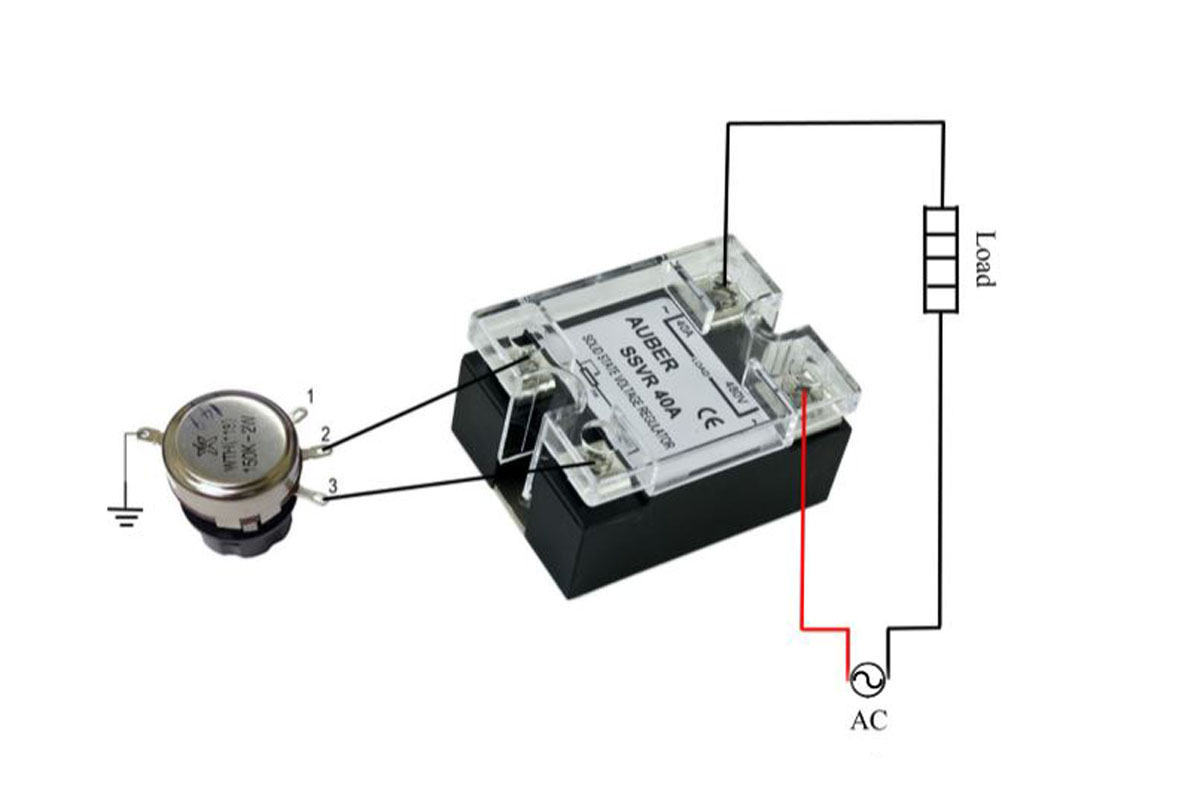
There is an image on the Auber website that is pretty helpful in how to wire the SSVR.

SSVR40A_s_4.jpg

I just realized that the wiring diagram I posted is incorrect - it shows pins 1 and 2 of the rheostat wired to the SSVR, not pins 2 and 3, as shown in the Auber diagram (and in the pics of the inside of my controller). The Auber diagram is, of course, correct, so I'll fix my diagram and upload it again.

Regarding the question of using an SSVR with a 120V coil, jhobson's response was correct.
 
Pogden,

Sorry I didn't see your questions - I'm subscribed, but for some reason didn't an alert. Anyways, here's what I'm doing:

Do you plug the power supply for your pump into a separate outlet, or did you add a 120V receptacle to your controller? Didn't add the 120V, separate plug/receptacle on a power strip for now - pump uses an old laptop brick for power, so it's a little clunky.
Do you any sort of a trub screen in the bottom of your keggle, or do you just let it all run into the fermenter? No trub screen - I use both the bag for the grain and then a hop spider with a similar bag for hops, so not much if any material in the wort. That litttle pump is easy to clog up!
Regarding the basket, does it actually fit down inside your keggle? If so, does it rest on the "lip" left where you cut out the bottom? Looks like a really tight fit, but it would be awesome if it works. How long does it take for the bag to drain, once you've raised it? Very tight fit, I'll see if I can dig up a picture. My buddy who helped with that part cut the top nearly to the edge of the keg itself. I let the bag sit until it stops, about 10 min, then last time I twisted/squeezed the hell out of it.
If you don't mash with your bag in the basket, do you just let it rest on the element while mashing? If not, how do you prevent it? I do mash with the basket in place, I just drape the bag all the way over the keggle, too. The recirc little pump is throttled to a trickle really, avoiding the stuck/stratified issues others have had with big March pumps.
Chilling the wort - I currently use my trusty immersion chiller that I bent to allow it to slide under/around the element (tricky as I can't see it and have to go by feel). I'm thinking of switching to a counterflow setup outside the keggle. I use that little pump to whirlpool, too, based on the Jamil chiller. Works great.


Again, sorry for the delayed response! Thanks again for inspiring this setup!
 
errudoh, a picture of your keggle/basket up close would be cool. How did you (or your buddy) manage to cut the hole that close to the edge of the keg? Plasma cutter?

I cut mine to fit the lid I bought using an angle grinder and a cutting disk. I got it too small (I was afraid to cut it too large, so I backed off my original measurement a bit; if I had just cut where I measured, it would have been perfect). I used a flapdisk sanding wheel to enlarge it a bit and now it fits my lid nicely. I'm not sure, though, how I could have made the hole as big as yours appears to be using the method I used.
 
He had a small air powered grinding disc that was able to get very close. I'll see if I can snap a picture or two tonight. There is maybe 1/2" of the original material left there.
 
Another question regarding your wiring. I noticed that in your wiring, you have the line in going first to the contactor, then to the SSRV which then leads to the element for heating. I've noticed in most of PJs wiring diagrams, that it goes line in to the SSRV, then to the contactor...which then goes to the element. Is there any particular reason for this? Or does it really not matter which comes first in the wiring?

Thank you.
 
I'm not and electrician, but I don't see any issue wiring it either way. Perhaps PJ has a preference, but I like seeing the contactor first. This way the SSR or SSVR does not always have voltage connected. The contactor acts as a switch so that no power goes to the SSVR unless the coil has power. Both the SSVR and contactor are rated for the appropriate amperage.
 
Cool, thanks for the explanation. I did some more research on the contactor last night and found some similar answers to what you just mentioned.

Thanks again man. It's appreciated.
 
I'm not and electrician, but I don't see any issue wiring it either way. Perhaps PJ has a preference, but I like seeing the contactor first. This way the SSR or SSVR does not always have voltage connected. The contactor acts as a switch so that no power goes to the SSVR unless the coil has power. Both the SSVR and contactor are rated for the appropriate amperage.

jhobson's right - I put the contactor first because with the main switch off, there's no power to the SSVR or anything else, which seems like the right way to do it. But I also agree that it could be done either way.
 
Back from the dead!

I'm looking to do something similar, but on a tighter budget, and I've got a few questions.

What effect does the potentiometer value have? Should this one work, or does it have to be 440kΩ?

If I want to use a different switch, I don't need the contactor, do I?
 
Last edited by a moderator:
If you want to save money the Still Dragon kit is about the cheapest way to get most of what you need. http://stilldragon.com/index.php/diy-controller-kit.html

As for the contactor if you find a switch that can handle the amps you intend to run at you don't necessarily need it. It's usually cheaper to buy a contactor and a cheap switch than to just a switch that can handle the current though. This contactor is only $12. http://www.amazon.com/dp/B004Z0RLR6/?tag=skimlinks_replacement-20

You could get by with a 30 amp switch safely enough which are easier to find reasonably priced than a 40 amp, but it doesn't cost much extra to use a contactor and cheaper switch to step up to 40 amp just for some extra safety factor.

You could also run the Still Dragon box with no switch at all where you'd just have to unplug it to remove power. Not how I prefer to do things but I'm sure many people do that.

Here's the controller I built to work with an external temp controller I have.

Thanks for the reply! I'm hoping this is somewhat temporary until I can get a pump and PID, but I don't think that's in the budget right now (although I need to get the brewhouse out of the kitchen). That's why I'll probably skip the switch or use a $10 240v 30A lightswitch for $10, skip the meter display, etc. I'll check the specs on that stilldragon and compare to the parts I'm shopping on Amazon (with 10% cash back on my Chase card!:ban:).

Edit: I think I can still do it cheaper on Amazon, but I need to know the pot value or if that makes a big difference, since stilldragon doesn't list that.
 
Last edited by a moderator:
The value of the potentiometer does matter. You should pick closest one you can find to what the SSVR calls for.

The potentiometer sets the time before firing via an RC timing circuit. At low R settings, the triac will get triggered early in the AC cycle, meaning more on time and higher power delivery. At high R settings, the triac will get triggered late in the cycle, meaning short on time and lower power delivery. If the pot has too low a value, you will be limited in how low you can turn down the power. A pot rated at half the specified ohms, will only let you turn the power down to about 50% of max power. If the pot has too high a value, the power will go to zero without turning the pot all the way, you will only be able to use a fraction of the pot's travel range. Anything rated within about 20% of the specified value should have reasonable usability.

Make sure the pot is rated for use at 240 volts, as it does see full line voltage during use. The wattage rating should also be at least 120,000 / R, where R is the resistance of the pot.

Brew on :mug:
 
I didn't mean to imply that the size the Pot doesn't matter just that the one he linked will work fine unless he has picked an odd SSVR. Most all of them on Amazon are 470K 2w or 470K-560K 2w and the Pot he linked to is a 470K 2W.
 
Back
Top