• Please visit and share your knowledge at our sister communities:
  • If you have not, please join our official Homebrewing Facebook Group!

    Homebrewing Facebook Group

Yet another Auber panel circuit question

Homebrew Talk

Help Support Homebrew Talk:

This site may earn a commission from merchant affiliate links, including eBay, Amazon, and others.

TheMadKing

Western Yankee Southerner and Brew Science Nerd
HBT Supporter
Joined
Jun 17, 2015
Messages
4,173
Reaction score
2,521
Location
Gainesville
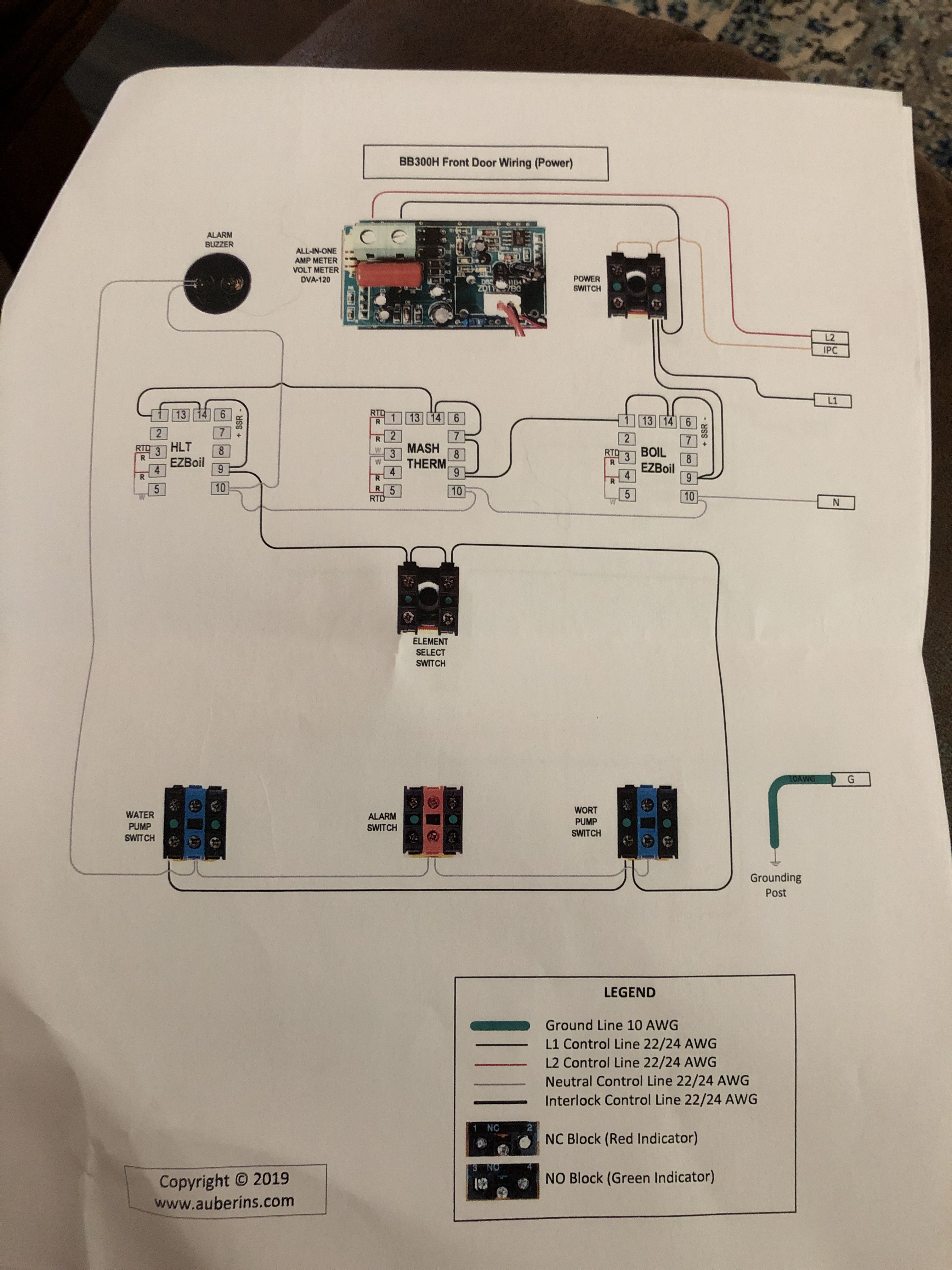
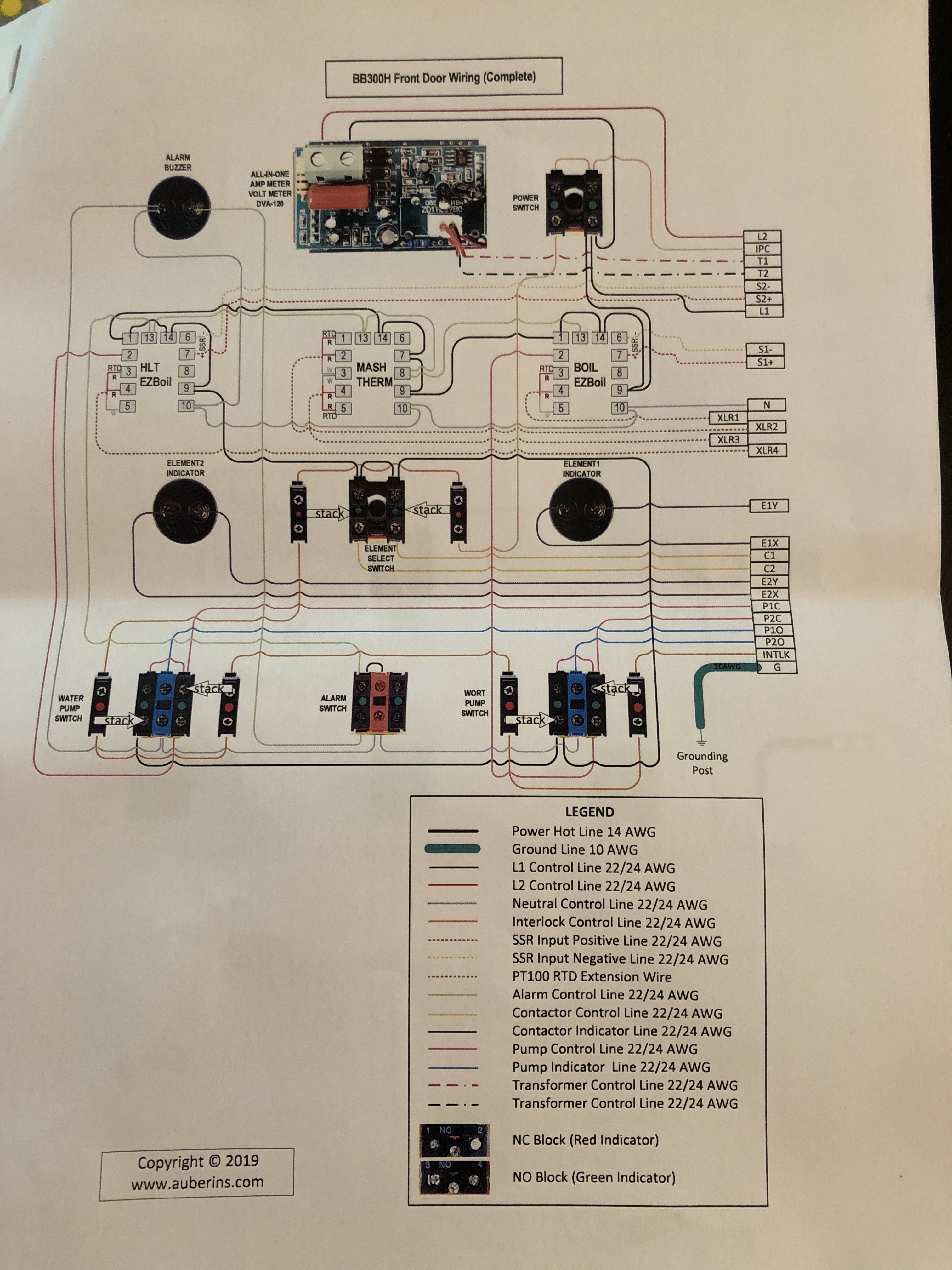
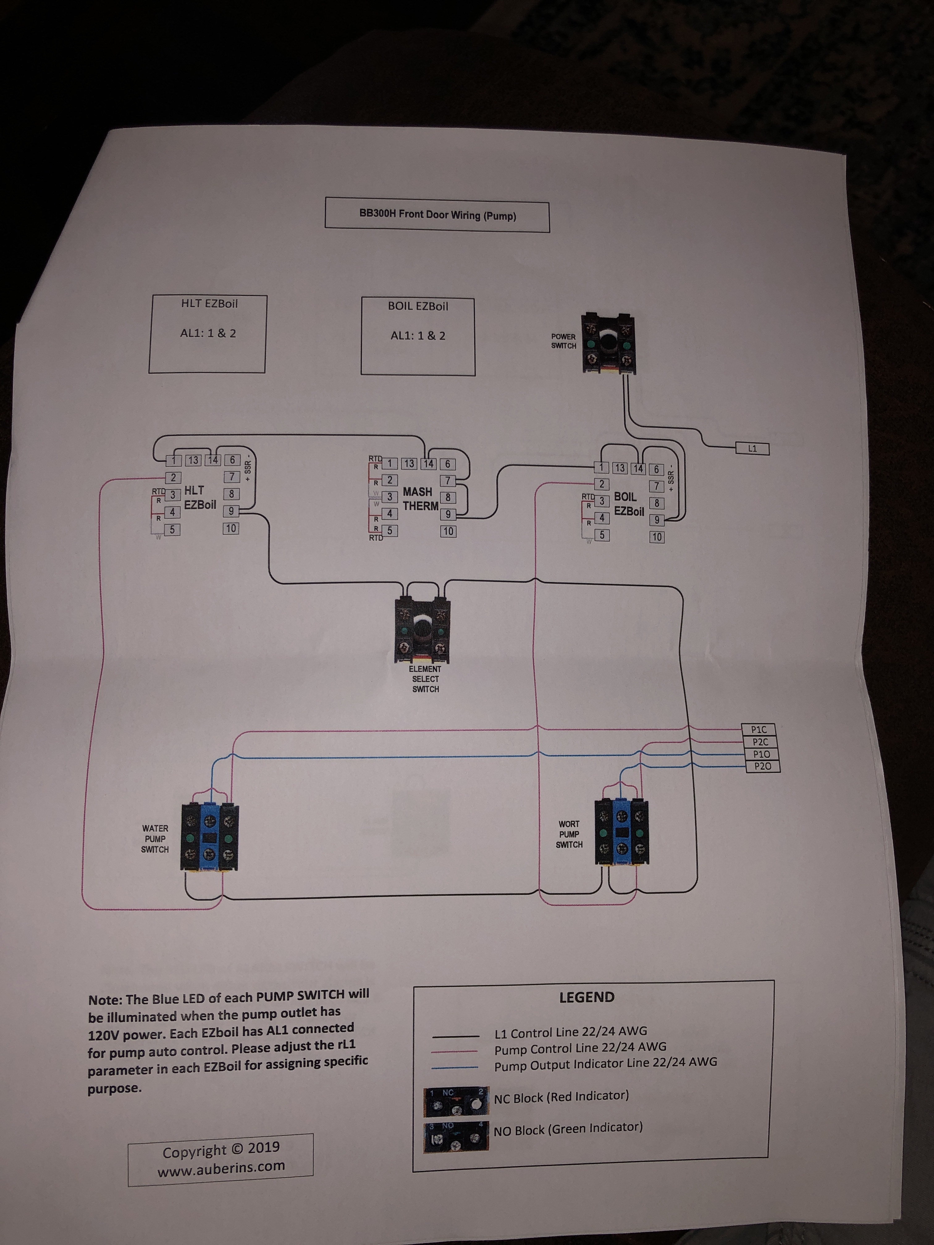
So I finally got my panel working. Everything seems work perfectly except for the pump switches.

I can't turn either pump on unless both pumps switches are turned on and then when both switches are on, both pumps run. So I can't operate them individually.

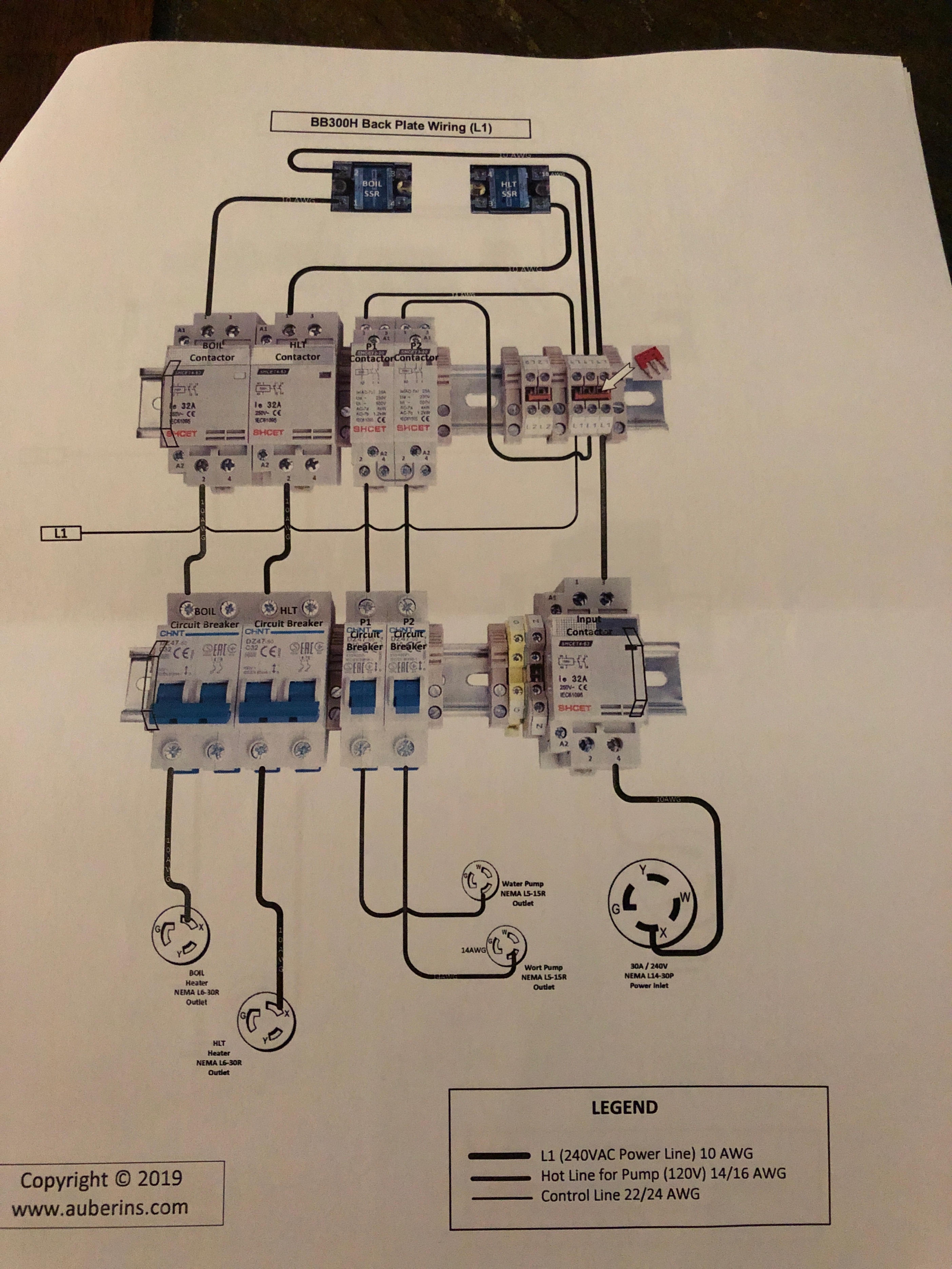
Both contactors fire individually when I turn the appropriate switch and I have verified that I have 120v at the power output plug hot wire on each individual pump plug.

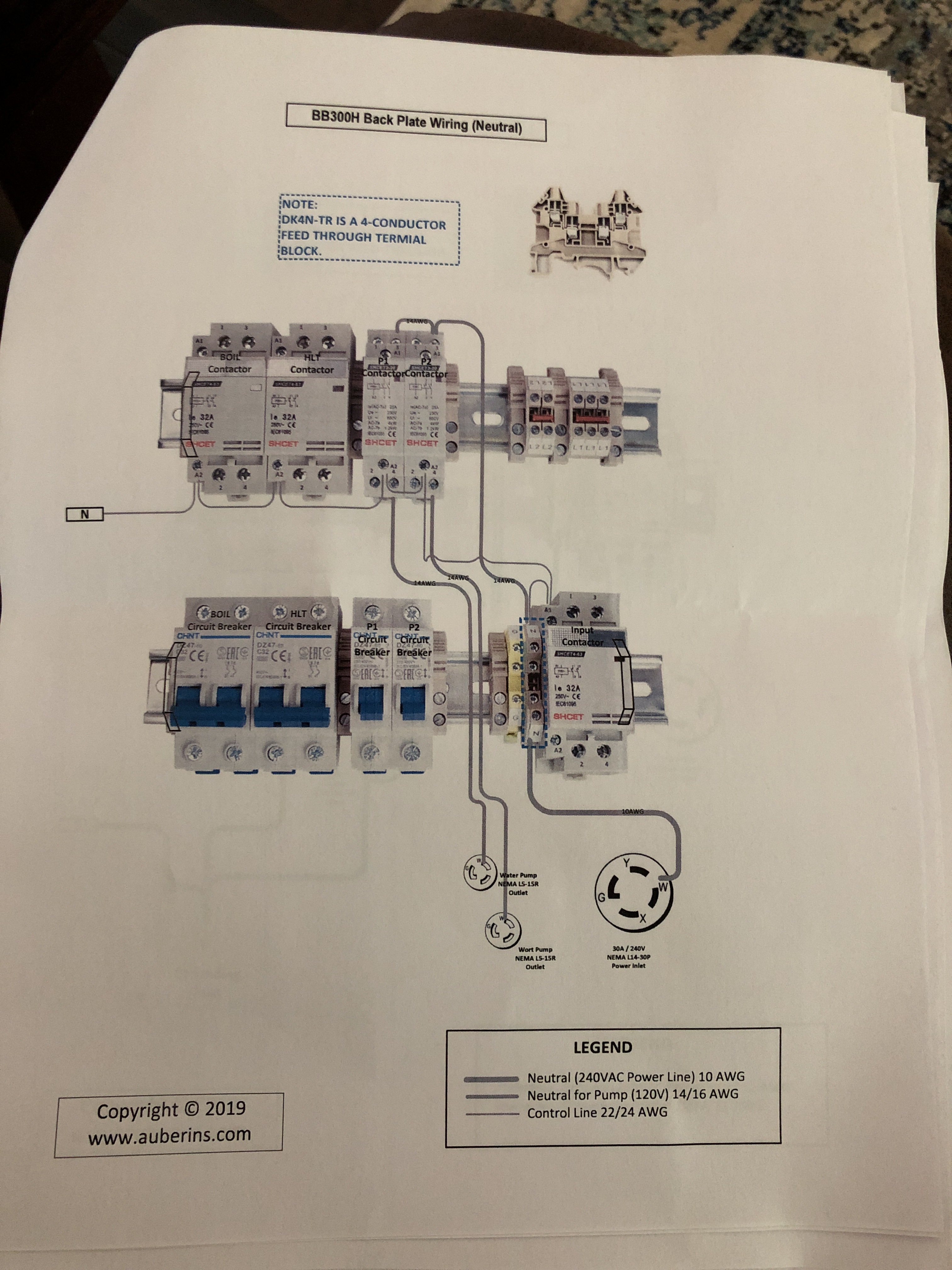
So I think that the issue is with the neutral line but I can't figure out what it is. I'm going to try replacing the contactors in case there's something wrong with them, but they both seem to be functional.

Any ideas would be appreciated!
IMG_6836.JPG


IMG_6836.JPG


IMG_6836.JPG
 
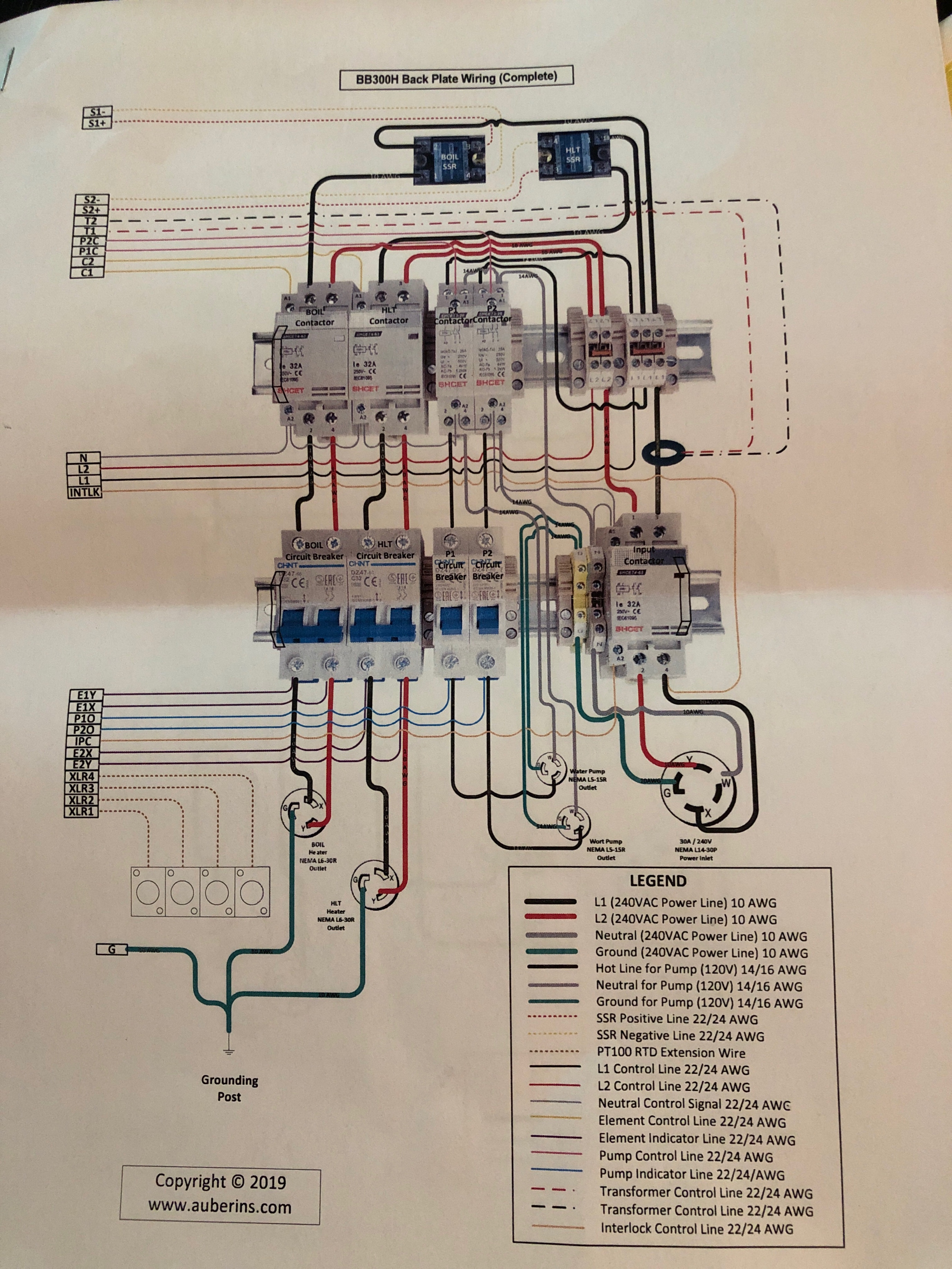
Where's the page showing the power wiring on the back plate?

Brew on :mug:

I figured it out

I reversed the contactors when I wired up the neutral wires coming from the pump output power plugs [emoji849].. So neutral for pump 1 is wired to the pump 2 contactor and visa versa

Stared at the drawing long enough to realize that's the only thing that could explain the behavior if I was getting 120v out
 
I am glad you got it working!
I find it interesting that Auber uses a contactor for a 2 amp pump. Seems unnecessary when the switch on the door is rated for 10 amps. Another thing I wonder about is running the neutral thru the contactor. Usually neutrals are not switched. Perhaps Doug or someone more knowledgeable than me can comment.
I thought the same things. In my opinion, there are two unnecessary contactors, and three unnecessary breakers (assuming the panel is fed from a 30A service with appropriate breaker and GFCI.)

Brew on :mug:
 
I thought the same things. In my opinion, there are two unnecessary contactors, and three unnecessary breakers (assuming the panel is fed from a 30A service with appropriate breaker and GFCI.)

Brew on :mug:

I was wondering about the breakers myself

It is indeed fed from a 30A GFCI that I installed in my panel so I considered removing them.

The switched neutral didn't occur to me. I think the main reason they used the contactors was so that the wire gauge in the bundle from the back plate to the front is never bigger than 22. If the pumps are wired directly to the switch I would have to run 14 awg across that bend where the door swings open.
 
Switching neutral for control purposes is generally a bad idea IMO. While it will work, changing back and forth between switched neutral and switched hot makes following diagrams and troubleshooting more difficult.
Most good designers place a value on consistency and simplicity in their designs.
One possible reason for using a control relay for the pumps is if the main switch doesn't have enough contacts to control the pump and control other things like an indicator lamp or a circuit interlock.
I did not examine the switch diagram closely, so not sure if that is the case here or not.
 
I was wondering about the breakers myself

It is indeed fed from a 30A GFCI that I installed in my panel so I considered removing them.

The switched neutral didn't occur to me. I think the main reason they used the contactors was so that the wire gauge in the bundle from the back plate to the front is never bigger than 22. If the pumps are wired directly to the switch I would have to run 14 awg across that bend where the door swings open.
I suspect you are correct about limiting the wire size that has to bend when the door is opened.

Brew on :mug:
 
Switching neutral for control purposes is generally a bad idea IMO. While it will work, changing back and forth between switched neutral and switched hot makes following diagrams and troubleshooting more difficult.
Most good designers place a value on consistency and simplicity in their designs.
One possible reason for using a control relay for the pumps is if the main switch doesn't have enough contacts to control the pump and control other things like an indicator lamp or a circuit interlock.
I did not examine the switch diagram closely, so not sure if that is the case here or not.
Agree that switching the neutral in a loop, rather than the hot, is a bad idea. Leaves the load energized even when "off." In this case they are using two pole contactors on 120V circuit branches, so they just decided to switch both hot and neutral - no safety issues there. The issue is that then "neutral is not neutral" as OP found, and you gotta keep the neutrals from different loops in the correct loop.

The switches they use can have up to 6 switch blocks if desired, in any combination of NO or NC, so that isn't why they used the contactors.

Brew on :mug:
 
Back
Top