• Please visit and share your knowledge at our sister communities:
  • If you have not, please join our official Homebrewing Facebook Group!

    Homebrewing Facebook Group

YABC-Yet a Brew Controller: BrewManiacEx

Homebrew Talk

Help Support Homebrew Talk:

This site may earn a commission from merchant affiliate links, including eBay, Amazon, and others.
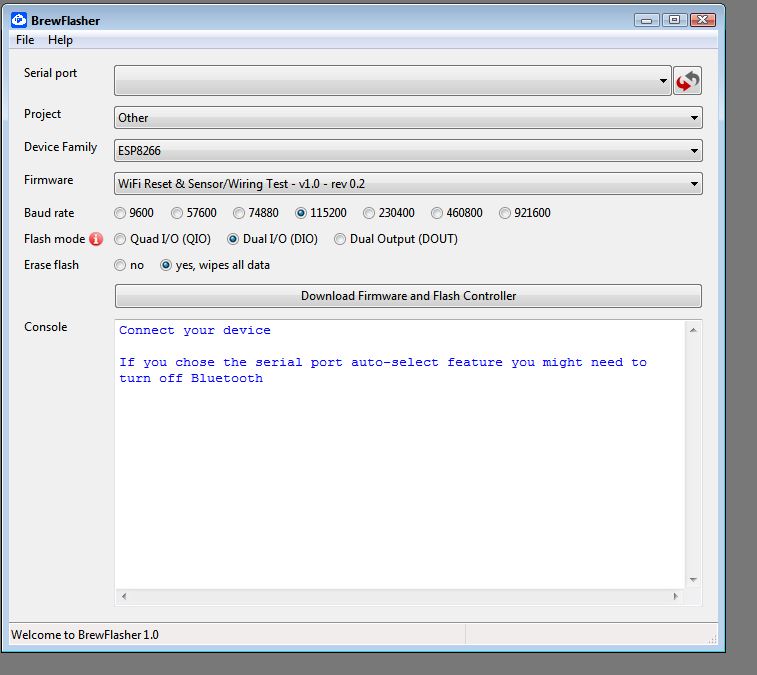
Since updating, I've been having connection issues where I can't connect at all via my router or directly to the AP (192.168.4.1). The page times out. I started from scratch, erased flash and re uploaded the 0.49 bin file and now have another problem. I am presented with the below page but when I click update, I get a "errror:connection refused" message. I tried ticking the 'Fresh install:Format SPIFFS and download all" option but after it formats, I get the same error. I tried reflashing again but get almost the same page but there is nothing under 'HTML/Javescript version: 0'. I reset the esp8266 but now can't bring up this page at all. Am I missing a step?
1598056342444.png
 
Just got it working again using PlaformIO and the full interface is available but after resetting the esp8266, I can't connet to it any more. The blue led on the esp8266 is flashing roughly twice a second.
 
I have been writing blank bin files to the entire address space prior to flashing again. Keep running into issues. Brewflasher doesn't have an option for BrewmaniacEX
 
I have been writing blank bin files to the entire address space prior to flashing again. Keep running into issues. Brewflasher doesn't have an option for BrewmaniacEX
There are a couple of steps that you need to follow - All you need BF for is to completely erase the esp8266 and get rid of the old wifi stuff- then use your normal program to load the .bin files
 
Ok thanks for that. Much easier to wipe flash that way. Still no luck. I can access the gui after flashing via PlatformIO and after I configure the access point to connect to my router I can access it via the static IP. As soon as the esp8266 is reset one more time, it is no longer accessible with the blue LED flashing roughly twice a second.

This is what I see in the serial monitor:

ets Jan 8 2013,rst cause:2, boot mode:3,0)

load 0x4010f000, len 1392, room 16
tail 0
chksum 0xd0
csum 0xd0
v3d128e5c
~ld
 
Last edited:
Is there a bug in the firmware regarding WiFi?
I just reflashed via ESP8266Flasher.exe again and set a static IP in my router instead of the brewmaniacex gui and after that I selected update now under 'HTML/Javescript version' and it updated without any errors. It is also still working perfectly after 10 power cycles.
 
The esp8266 has 4M or 16M(pro version) of flash. Web server, db for loging and pages for UI. Hard time filling 256k???? Bet he's into a couple meg.
it's the libs that kill you. nothing is written anymore to conserve memory.. Sad that those of us who cut their teeth on 4-8(expensive)k of ROM get back into some of these boards and (I guess I'm grateful for those that do the low level $#!+ these days..) find that nothing is done without .5-2M of space, maybe we need to go back to 7bit bytes?
4-16M of space is a lot.. don't waste it..
(yeah, oldish guy here)
 
I'm about to start ordering parts for the pcb and I'm wondering about the phoenix contacts. Am I correct in assuming that any old phoenix contact with a 5.08mm pitch will work?
 
I think i may have som v1.1 boards, i have to check tomorrow. Cannot remember what the changes was to 1.11 though. Probably som small error just. So long since i built my two boards.

you are also based in Sweden, if so i can probaby send you a board for a small fee. drop me a pm.
 
Hi RollE2k

Thanks for the reply.

My LCD works fine. I am trying to see the effect of the buttons on the LCD.

I have a 4-button membrane setup. Plugging this into the headers and pressing buttons does not seem to cause anything to happen.

I have a PCF8574P soldered next to the D1, so there shouldnt be any issues there either...

I have enabled the ButtonViaPCF8574 flag and scanned the I2C addresses. I have then tried all the available addresses within that flag, but i have not been able to get the buttons working.

I have even shorted these headers directly to make sure the buttons are not defunct.

Any ideas?

H Ender2336,

Did you ever find a resolution to your buttons issue? I have the same problem and so I'm currently looking for a solution.
 
Hello. Has anyone rewired a Klarstein All in One using BrewManiac ?

It has basically 2 Heating Elements and a Pump.
I guess I should declare the 1800W as Sparge Heating and the 700W as the Heating and I'm good to go ?
I want to add a motorized paddler as well. I'm thinking about putting it together with the pump.
Do I have another option ?

1614267684020.png
 
H Ender2336,

Did you ever find a resolution to your buttons issue? I have the same problem and so I'm currently looking for a solution.

To close this, I did find the resolution. I used the wrong port PCF8574AP port expander, but replaced it with PCF8574N. Both were purchased as PCF8574P on AliExpress and EBay, but the actual versions were different. I believe the addressing between the circuits differ.
 
Hello. Has anyone rewired a Klarstein All in One using BrewManiac ?

It has basically 2 Heating Elements and a Pump.
I guess I should declare the 1800W as Sparge Heating and the 700W as the Heating and I'm good to go ?
I want to add a motorized paddler as well. I'm thinking about putting it together with the pump.
Do I have another option ?

View attachment 719971
 
I just finalized BrewManiac for my all-in-one system, and I have connected 2x 1250w elements in parallel. It was however just finalized, so I have not been able to test it yet. If you decide to do it, I have created an enclosure to be 3D-printed. You can find this here: BrewManiac Control Box by Geirn
 
I just finalized BrewManiac for my all-in-one system, and I have connected 2x 1250w elements in parallel. It was however just finalized, so I have not been able to test it yet. If you decide to do it, I have created an enclosure to be 3D-printed. You can find this here: BrewManiac Control Box by Geirn
Nice. Do you have photos of the wiring/connections under the boiler? Interested to see.
 
Nice. Do you have photos of the wiring/connections under the boiler? Interested to see.

Yes, I obviously replaced the very minimalistic all-in-one electronic board (with on-board PSU and relays) with a separate 12V PSU and 2 SSR relays, whereof the one to the heating elements is with heat sink. I fixed it all to the side of the base. I’m still connected to the physical pump switch, as I was thinking of being able to turn of the pump during mashing to stir, even in automatic mode. However, this might be possible from the controller too(?)
 

Attachments

  • 92276A0D-D7E0-47EF-A69B-36E46954678C.jpeg
    92276A0D-D7E0-47EF-A69B-36E46954678C.jpeg
    1.7 MB
@Singing Indurain (love that nickname) : It's a Klarstein then ? Looks promising for what I want to do :D
He-he, came to think about that name while I was exercising on my bike in the rain😉 
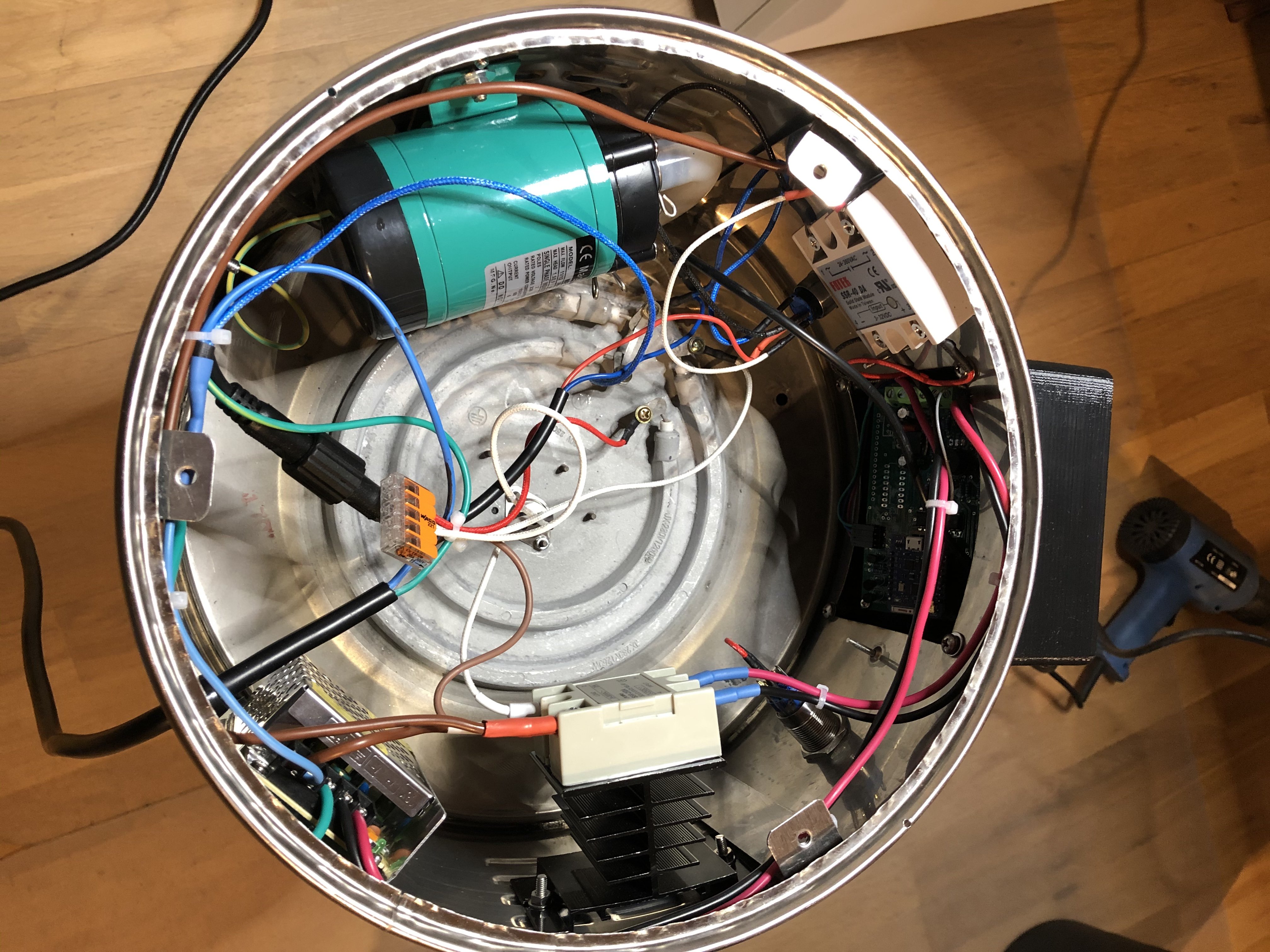
I’t not a Klarstein, but I suppose they are not that different. This is a BB30 Automatic, that I believe was maybe just sold in Norway. I bought it with broken electronics for this purpose. You can see it here:
 
Yes, I obviously replaced the very minimalistic all-in-one electronic board (with on-board PSU and relays) with a separate 12V PSU and 2 SSR relays, whereof the one to the heating elements is with heat sink. I fixed it all to the side of the base. I’m still connected to the physical pump switch, as I was thinking of being able to turn of the pump during mashing to stir, even in automatic mode. However, this might be possible from the controller too(?)
Thanks for that. I still need convert my urn and was unsure how the SSR and pump would handle being so close to the underside of the elements. I will definitely print your electronics enclosure, cheers.
 
OK for the life of me I cannot find a 7805DT in TO252 package. What should be the specs for the voltage regulator ? 5V output. What should be the max I output ? Is 100 mA enough ? Shall I go to 1500 mA ?
 
OK for the life of me I cannot find a 7805DT in TO252 package. What should be the specs for the voltage regulator ? 5V output. What should be the max I output ? Is 100 mA enough ? Shall I go to 1500 mA ?

I have not really reflected over required specs, but I ordered TO263 packaging (without actually realizing). It is a bit big, but it works fine and I was able to mount it by cutting/modifying its pins. I ordered this:
https://a.aliexpress.com/_mrw0AGb
 
I just bought that : https://www.reboul.fr/storage/0000309c.pdf
I might have to bend some pins but I guess it should do the trick.

Edit : It did. Moving forward....
Haven't connected a screen though

Edit 2 : Screen connected, Got Web, attached to Network, can do stuff. Can't see anything on screen though.

Edit 3 : Using the "small I2C board at the back of the screen", will remove IC3 (or small board at the back)
1614962963657.png
 
Last edited:
OK for the life of me I cannot find a 7805DT in TO252 package. What should be the specs for the voltage regulator ? 5V output. What should be the max I output ? Is 100 mA enough ? Shall I go to 1500 mA ?
Search for LM7805 and 78M05
 
Ok quick update (and call for help).
I get it all up and running, have a dual heater setup.
Pump work, Heater 1 get 11 or so volts on the HTR/ACT1 and LED.
But when I am in BOTH or Heater 2 only, I only got something like 3 Volts on the SHTR/ACT3 & LED outputs.
Did I swap resistors ?
1615579385210.png
 
OK I rechecked everything, doing everything back step by step. I ckecked my BC337s, my diods, my Rs,nothing fried.

My issue is that nothing happens on the D8 Pin of the D1 Mini when I trigger ACT3/Secondary Heater.
On D7, I have the 0 to 3.3V trigger happening, same on D5 for the pump.
But D8 stays at 0 all the time.


Could it be a Defective D1 ? Where JUST this would be broken ?
 
Back
Top