EyeofdaHawk
Well-Known Member
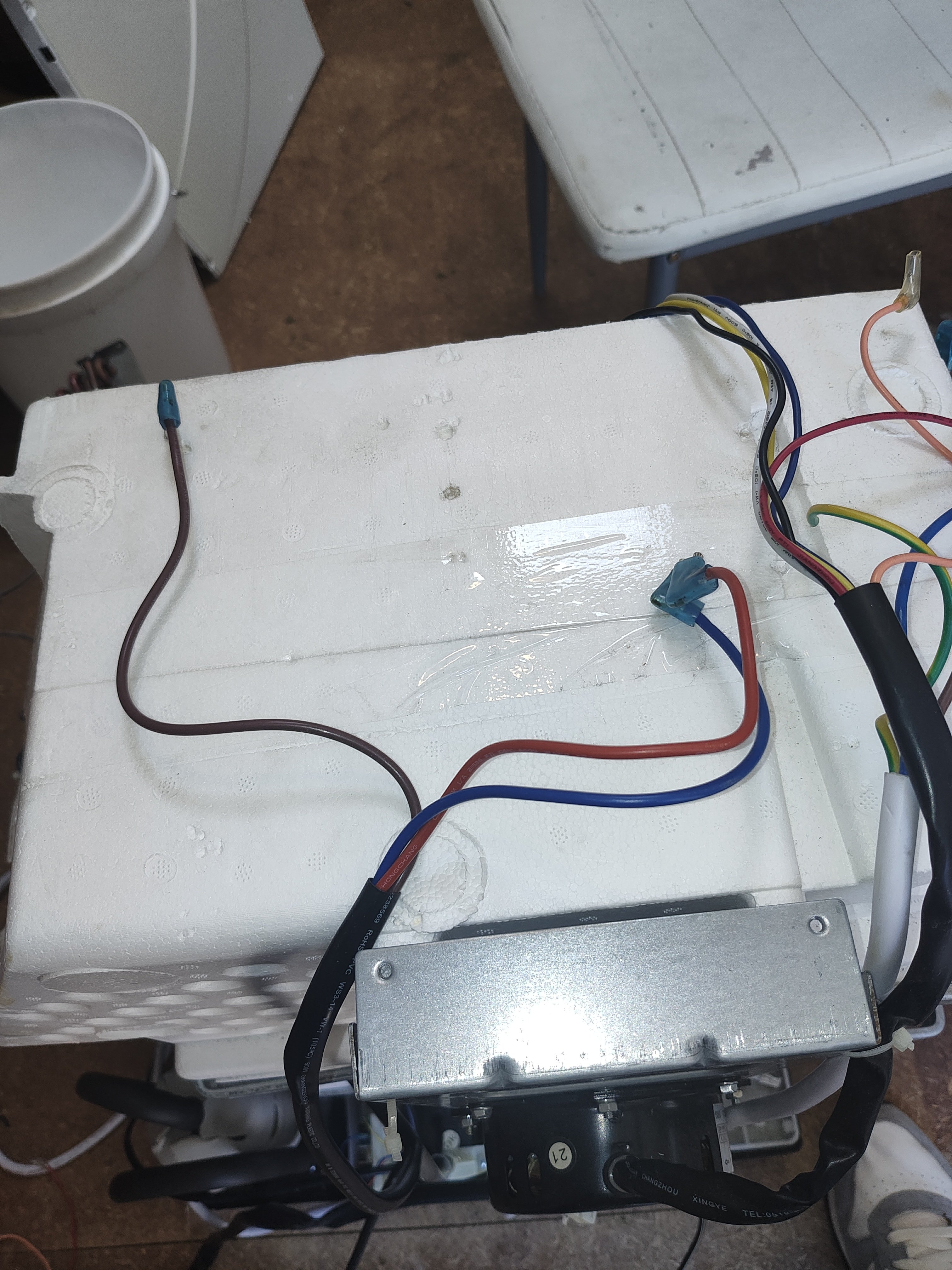
Hi all
Trying to figure how to wire a air con compressor to an inkbird.
I'm in Aus so we use different colouring, but i'm struggling to even find what the colours represent (not even sure they're US colours).
As far as i can tell, red is live, blue is neutral and brown is also live? I think i'd also need a ground, any suggestions here?
Thanks
Hawk