Wiring for an electric boil kettle

Homebrew Talk - Beer, Wine, Mead, & Cider Brewing Discussion Forum

Help Support Homebrew Talk - Beer, Wine, Mead, & Cider Brewing Discussion Forum:

This site may earn a commission from merchant affiliate links, including eBay, Amazon, and others.

BigFatDad

Active Member
Joined
Feb 12, 2020
Messages
31
Reaction score
21
Location
WI
Hey all,
I've been brewing for about a decade on propane and I've been looking to go electric to escape the balmy WI winters. I am new to posting on homebrew talk, usually I just read and absorb.
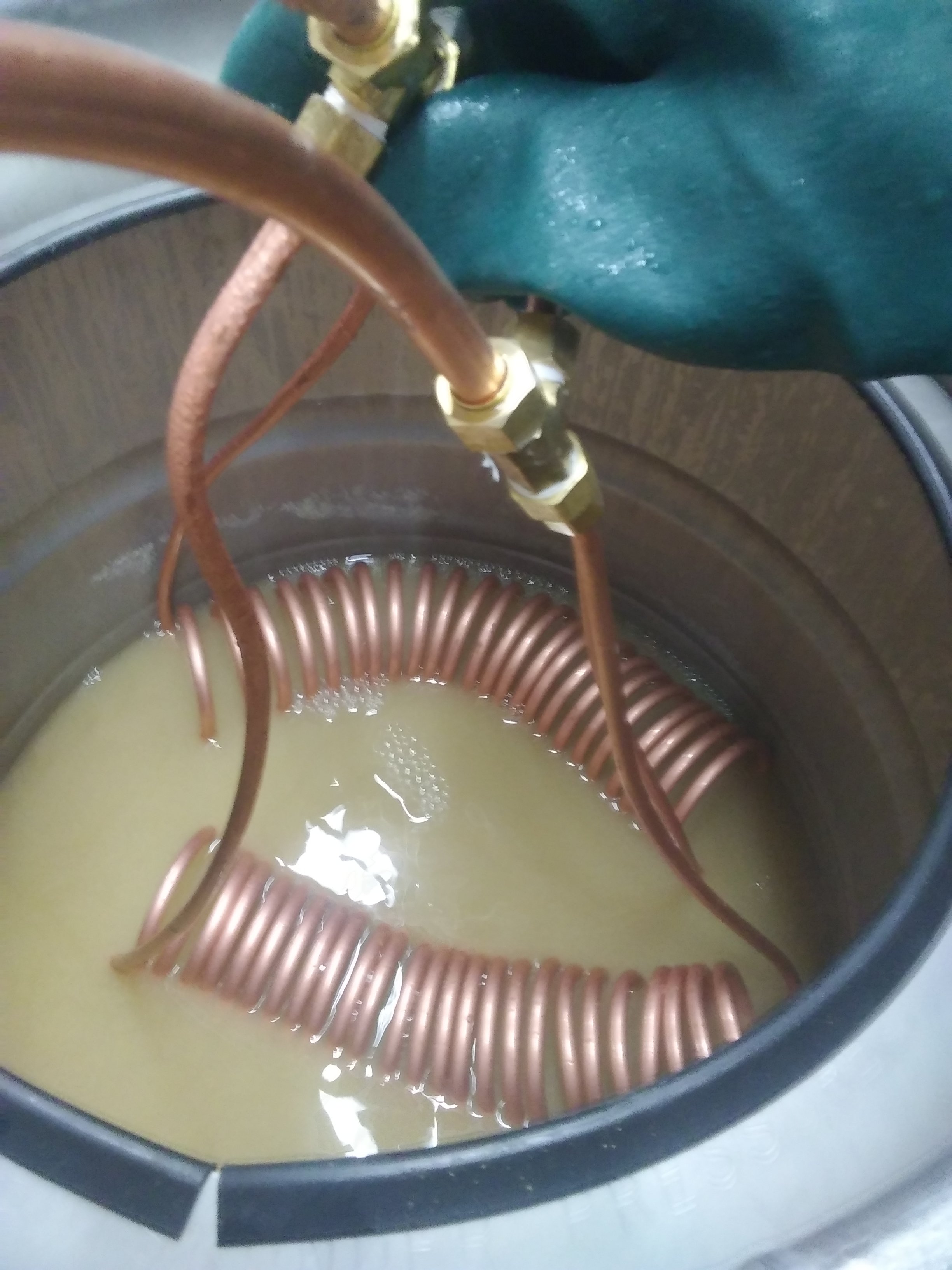
I typically do a no sparge method where I heat the water in the boil kettle, gravity drain to mash tub (cooler), then drain/ pour wort I to BK. I am looking to do the same thing with electric.
I have been scouring the HBT electric brewing threads and found a few I think would work for what I am trying. I have read Kal's site and that's awesome but I don't have the space nor desire for a 3 kettle system.
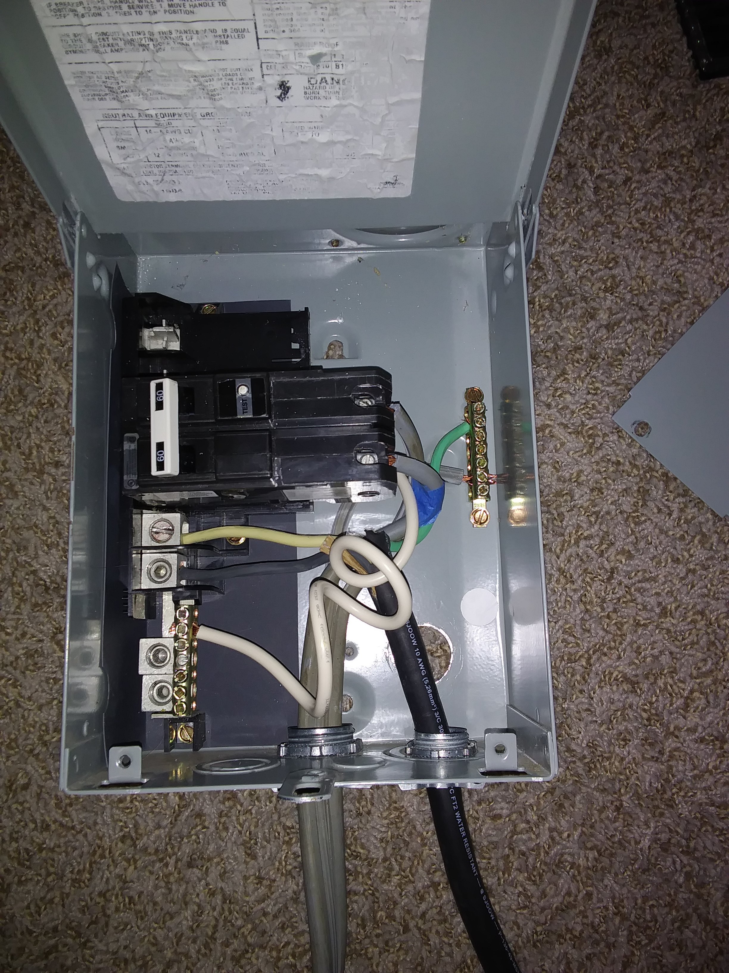
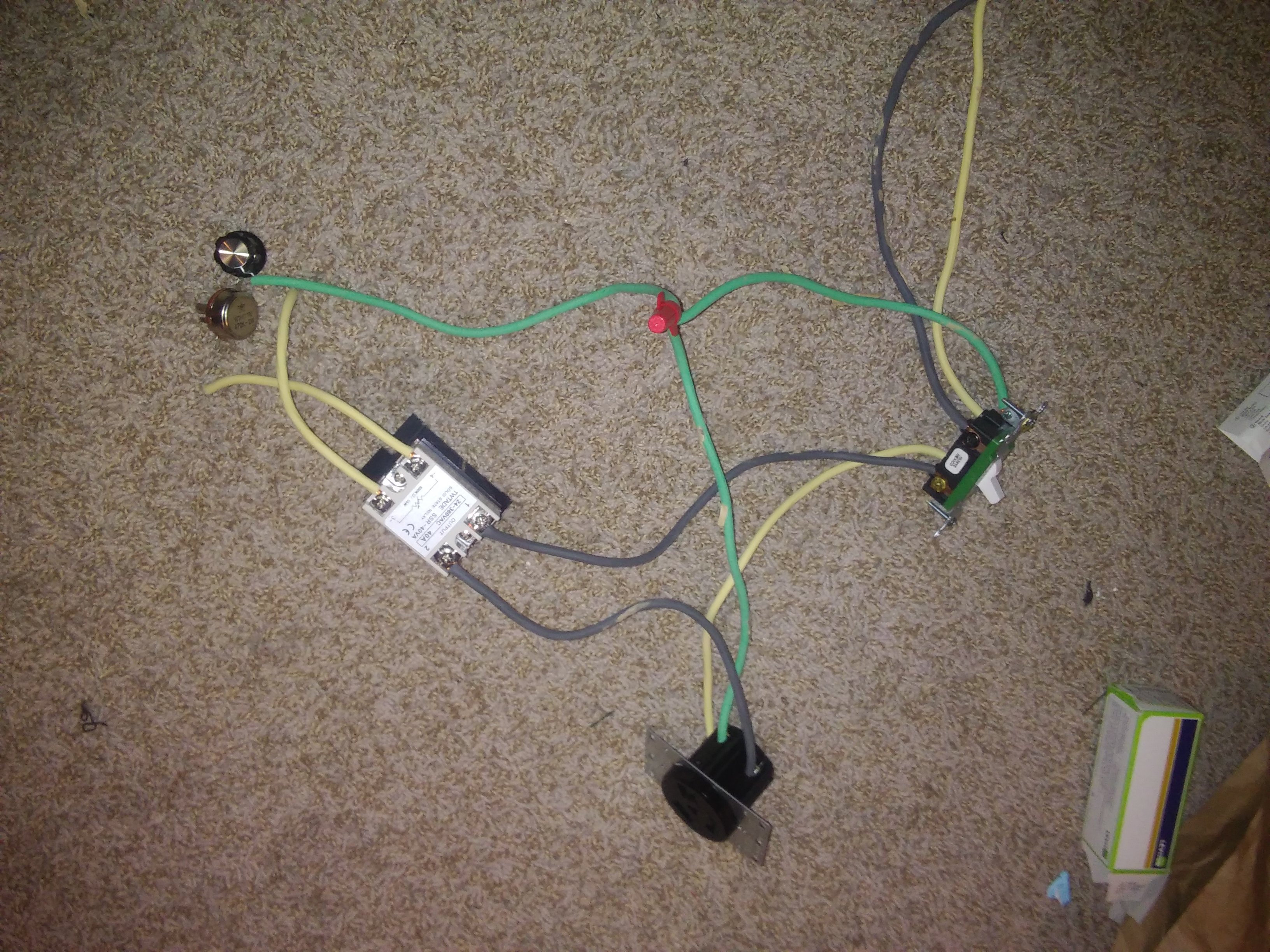
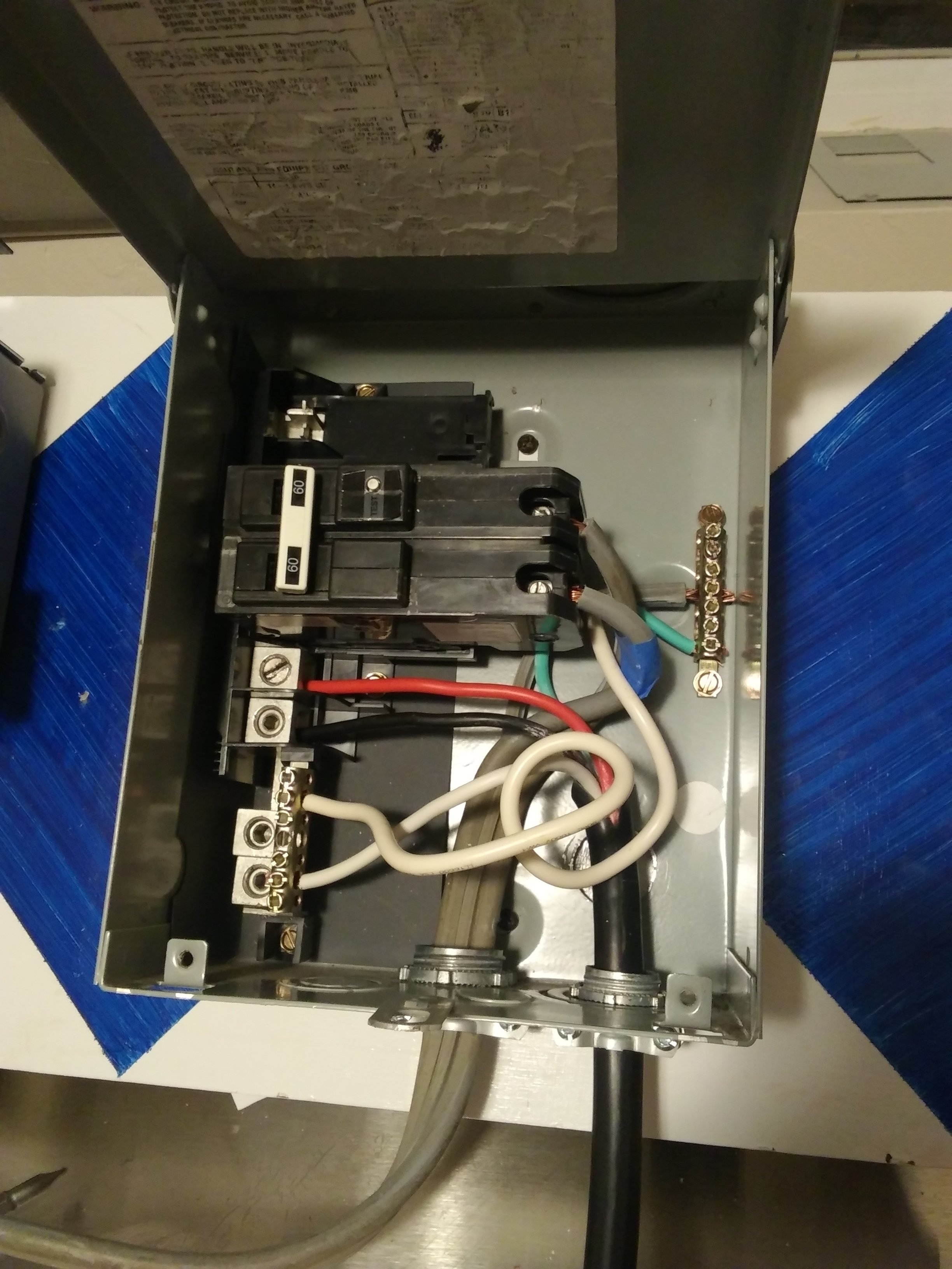
I have a few posts on here that are close to what I'm thinking. I have a few pictures to help explain what I want to do. The wiring diagram is from here, I forget the exact thread or author (sorry). Then I have the 30a gfci box and wiring and finally the laid out ssvr wiring then all of it in a box.
I tried testing this with the dryer and found out dryers and gfi don't get along. Like a trip every time kind of relationship. I have stainless elements in the mail but I'm wondering if this looks correct? If not I want to have it ready to go so when the elements come in I can a water test fairly quickly.
All plugs are standard 3 prong dryer plugs. I will wire another one to the element 5500watts.
Thanks for your knowledge and creativity!
 

Attachments

  • 20200126_184321.jpg
    20200126_184321.jpg
    610.5 KB · Views: 177
  • 20200212_144219.jpg
    20200212_144219.jpg
    1.4 MB · Views: 174
  • 20200208_125653.jpg
    20200208_125653.jpg
    1.4 MB · Views: 163
  • 20200212_153958.jpg
    20200212_153958.jpg
    1.2 MB · Views: 166
  • 20200212_144432.jpg
    20200212_144432.jpg
    1.3 MB · Views: 162
  • 20200212_144332.jpg
    20200212_144332.jpg
    1.2 MB · Views: 162
Well I talked to an electrician and got it all wired up. I have made 4 batches with this setup. I went from a counterflow chiller to an immersion chiller to speed up cleaning. My normal brew day on gas with a no sparge method was 3 hours from gas on the all put away. I have now been closer to the 3.5-4 hour range. I will keep making tweaks to see if I can get closer to the 3 hour mark. 20200301_135500.jpg 20200307_184047.jpg
 

Attachments

  • 20200412_114325.jpg
    20200412_114325.jpg
    662.6 KB · Views: 83
Have you tried the "Test" button in your spa panel? They way you wired the spa panel, I don't believe the "Test" button will trip the breaker as it should. The GFCI should still protect you, but you have no way to test it.

BTW, I am the designer for the schematic that you posted. It is just one of many that I have posted on HBT.

Brew on :mug:
 
Thanks for the design! You are correct, that picture is not accurate, I will post one when I get home about how the GFCI is now wired. It is a lot nicer brewing in the basement than outside when its snowing.
 
Here is what it looks like now. View attachment 675703
I can't really tell where the pig-tail from the GFCI breaker is connected. In a four wire system, it should connect to the neutral bus. In a three wire system, it should connect to the ground bus. If not, the breaker test button will not work.

The test button operates by shunting a small current from one of the hot lines to ground or neutral. This causes an imbalanced current thru the differential current sensing coil, which trips the GFCI. That small shunt current goes thru the white pigtail. If the pigtail is not connected to ground/neutral, then no current will flow, there will not be a current imbalance, and the GFCI will not trip.

Brew on :mug:
 
So I tried the test button. It did not trip. Once I put the pigtail on the ground bar, then it did. It's a 3 wire system. Thanks!
 
So, we moved and now (per code) there is only 4 prong outlets. Can I simply wire a 4 prong input to the spa panel and continue to use the same controller? My thought is yes, I am struggling to find a wiring diagram that has 4 wire into spa panel and 3 wire out. Thoughts?
 
So, we moved and now (per code) there is only 4 prong outlets. Can I simply wire a 4 prong input to the spa panel and continue to use the same controller? My thought is yes, I am struggling to find a wiring diagram that has 4 wire into spa panel and 3 wire out. Thoughts?
Yes. Just wire the neutral from the input cord to the neutral bus of the spa panel. The white pigtail from the GFCI breaker should be moved to the neutral bus, if it had been connected to the ground bus. Make sure the neutral bus has no connections to the ground bus. Be sure to make sure the "Test" button on the GFCI still works before you use the brew system.

Brew on :mug:
So could I be even lazier and just plug this into the wall, then the current set up into that?
https://www.amazon.com/Certified-Ap...g+dryer+cord&qid=1605009952&sr=8-4&th=1&psc=1
 
Yes, you can wire that cord into your spa panel replacing the current 3 wire cord. You still need to make sure the insides of the spa panel are wired correctly (no connections between neutral and ground internally.)

Brew on :mug:
OK, I think I got it. Look correct? I pushed the test button and it does trip the breaker.
 

Attachments

  • 1605235793027713908125.jpg
    1605235793027713908125.jpg
    781.6 KB · Views: 38
Looks good to me.

Brew on :mug:
So I have been using this controller now for a few months without issue. However, I was reading some other electric brewing posts about failed ssrs and stuff. If the SSR on this design (running a rheostat) fails, how will I know? Will only the GFI trip? Also, since we moved, I brew on a stainless table with a spike kettle and a triclamp holding the element in place. The element is grounded, does that mean the kettle is grounded as well? Do I need to ground the table? I never even thought of these things until reading those posts. Is there anything else safety wise I might still be missing?
 
So I have been using this controller now for a few months without issue. However, I was reading some other electric brewing posts about failed ssrs and stuff. If the SSR on this design (running a rheostat) fails, how will I know? Will only the GFI trip? Also, since we moved, I brew on a stainless table with a spike kettle and a triclamp holding the element in place. The element is grounded, does that mean the kettle is grounded as well? Do I need to ground the table? I never even thought of these things until reading those posts. Is there anything else safety wise I might still be missing?
The Tri-clamp will electrically connect the kettle to the element body. So, as long as the element body is grounded, the kettle will also be grounded. The only exception would be if you used a weldless Tri-clamp fitting on the kettle, AND used a rubber washer on BOTH the inside and outside of the kettle. This is not how weldless fittings should be done.

It is considered good practice to have metal tables grounded as well. You can ground the table separately from the kettle, that way you won't have to worry about the kettle being tethered to the table when it comes time to clean it.

You could put an indicator lamp in parallel with the element (after the SSVR.) This light will dim as the power setting is lowered, but if the SSVR "latches" or fails on, then the lamp would be on full brightness no matter what the power setting. This wouldn't be a particularly sensitive indicator however.

Another indicator would be a voltage meter in parallel with the element. If the meter reads full voltage at less that full power settings, then the SSVR has failed.

Brew on :mug:
 
Back
Top