Wiring Diagram for (2) 5500w wired to (1)PID?

Homebrew Talk - Beer, Wine, Mead, & Cider Brewing Discussion Forum

Help Support Homebrew Talk - Beer, Wine, Mead, & Cider Brewing Discussion Forum:

This site may earn a commission from merchant affiliate links, including eBay, Amazon, and others.

SirJoshuaIV

Well-Known Member
Joined
Mar 3, 2012
Messages
61
Reaction score
4
Location
Delhi
I want to thank everyone in advance for the help on this. I have used this forum many times as a reference tool, and have great respect for everyone one here. It wasn't until now that I couldn't find what I was looking for, so I am now making my first post for help.

I am in the process of upgrading my current brewing system. I currently use a 3 vessel system that is has a sanke as my mash, and one for the HLT. I use a 15 gallon polarware for my boil kettle. The system is heated by propane. For my new system, I am building a 1bbl HERMS system, and plan to go all electric with this build. I will be using the boilermaker 55g for the kettle, and (2) 40 gallon kettles for the MT and the HLT.

The boil kettle will be heated with (2) 5.5kw elements, controlled by a single rotary voltage regulator, in it's own control box. This will be running off its own 60 amp breaker. My dilemma is finding a wiring diagram that will work for my HERMS, I am semi familiar with electrical, but not enough to jump into this with out a good diagram to work off of, with minor modifying if needed.


I am planning to heat the HLT with (2) 5.5 kw elements, or a 4.5kw and a 5.5kw, run off a 60amp breaker (separate from the boil). I would like to wire both elements to a single PID controller that will be able to turn them both on or both off depending on the set temp. I would also like to have rocker switches to be able to manually shut off each element. The mash pump will be controlled by a separate PID controller that has its own rocker switch.

Does anybody have a diagram for something similar to this? The only one I can find is for a (2) 2kw element system, (2) pumps, and a single PID, all run off 120. http://imageshack.us/f/194/auberinwiring1a4simple1.jpg/
 
So I have found a diagram that I believe I can use to base my plans off of for at least controlling the HLT elements ( adding a PID for the MT and pump should be easy) I will be powering the control box off a 60amp spa panel, so I will have adequate amperage coming into the box.

Here is my question: Can I simply eliminate the selector switch between the two heating elements and increase the SSR amerage to 75a or 100a? Would it be better to use (2) 40 amp SSR's and use a jumper from the PID to both SSR's? Any ideas or existing diagrams that may work for this? Also, I will be eliminating one of the pumps, since this control box will be dedicated entirely to the MT and HTL

http://www.pjmuth.org/beerstuff/images/Auberin-wiring1-a4-5500w-30c.jpg
 
Just connect both to the same SSR or use 2 SSRs. Either way it won't matter much. One SSR is a tad simpler.
 
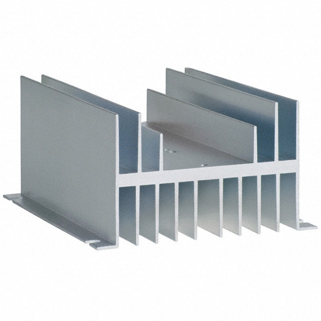
One thing to consider - a SSR dissipates about 1 watt per amp. With a single 5500 Watt element you are looking at about 23 watts & with two elements you will double to 46 watts. Your SSR heat sink has to dissipate all of that wattage.

In other words, make sure your SSR heat sink is large enough and you will be OK.
 
Is there a heat sink that you would recommend for that? I was planning on using an old cpu heat sink that has a cooling fan attached to it. I would imagine this would be sufficient, what are your thoughts?
 
Your SSR is designed to bolt onto a mounted heat sink or thick panel that acts like a heat sink while a CPU heat sink is designed to fasten to what it's cooling. How are you going to fasten them together and how will you mount them?

These are already heat sinks designed for SSRs.
 
The cpu I have is an old style that has a set of clips, that could be modified. But just typing up my plans of drilling and adapting them seems like more of a hassle than its worth. Im all about saving money, but I think i'll go with one already made! Thanks for the advice!

I will still probably use the CPU fan, it will just be used now to vent and cool the project box.
 
I am planning to heat the HLT with (2) 5.5 kw elements, or a 4.5kw and a 5.5kw, run off a 60amp breaker (separate from the boil). I would like to wire both elements to a single PID controller that will be able to turn them both on or both off depending on the set temp. I would also like to have rocker switches to be able to manually shut off each element.
Referring to the sentence above I highlighted: Why do you want the switches? Is it to physically cut power to the elements for safety reasons? (I do this on my setup). In which case you only need one switch to do both (not two).

Rocker switches with that high current capacity are basically impossible to find. You need to use a high power relay or contactor that "remotely" controlled by a lower power switch.

Kal
 
Referring to the part below I highlighted: Why do you want the switches? Is it to physically cut power to the elements for safety reasons? (I do this on my setup). In which case you only need one switch to do both (not two).

Rocker switches with that high current capacity are basically impossible to find. You need to use a high power relay or contactor that "remotely" controlled by a lower power switch.

Kal

I agree, find some SSR's that are controlled with low voltage and and switch the low voltage with rocker switches. I used 3 position switches and set them up for "manual on, off, timer on" so I can turn them on and off manually or set them to turn on automatically with a timer.
 
Is there a heat sink that you would recommend for that? I was planning on using an old cpu heat sink that has a cooling fan attached to it. I would imagine this would be sufficient, what are your thoughts?

This is what I used. Very good heat dissapation (0.7C/W rise over ambient). You can mount 2 SSRs to it.

http://search.digikey.com/scripts/DkSearch/dksus.dll?vendor=0&keywords=CC1702-ND
MFG_HS072.jpg
 
It was simply for safety purposes. I want to be able to ensure that both legs are killed in case something shorts. Do you see any added benefit to this? I had thought about putting the rocker switches before the SSR's, still debating it.

What about using 30 amp DPST switches, one for each element? There are just so many ways to wire up a control box!
I (and many others here) put 30 amp relays after the SSRs controled with a simple switch exactly for this safety reason: To ensure that there's a true physical (mechanical) disconnect when you want the elements to be off to sure. SSRS tend to fail closed and are solid state switches with some leakage current.

A 30 amp switch is also possible but they're not easy to find/tend to be big. Most will use contactors or relays instead that are controlled buy a low power switch the operator uses.

Kal

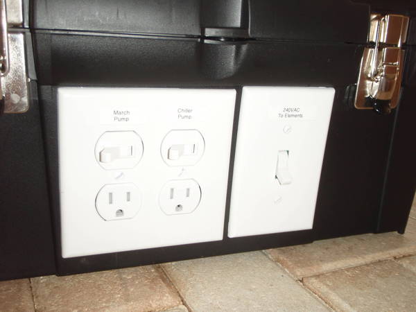
Home depot has this switch which I used on both my toolbox control panel and the 240VAC supply from the wall. The switch on the toolbox allows me to turn off all power to the elements while leaving the 120V outlets and the PID alive. The one on the wall is inside a waterproof housing.

Leviton_30A_240V_DPST_Switch.jpg
Toolbox_Front_Panel.JPG

240V_power_switch.JPG
 
I (and many others here) put 30 amp relays after the SSRs controled with a simple switch exactly for this safety reason: To ensure that there's a true physical (mechanical) disconnect when you want the elements to be off to sure. SSRS tend to fail closed and are solid state switches with some leakage current.

A 30 amp switch is also possible but they're not easy to find/tend to be big. Most will use contactors or relays instead that are controlled buy a low power switch the operator uses.

Kal

Thanks Kal! you've been a lot of help.
I was thinking of going with a contactor coil after the SSR, since I have seen many diagrams using these and I am more familiar with them. Then I could use the switch to cut a leg to the contactor coil.

Do you have recommendations for a good contactor, or a relay? I can find them pretty cheap on Ebay. However, I would much prefer spending a bit more money if it means safer and less problems down the road. Also would it be better to have one for each element, or just a single 50 amp?
 
Back
Top