• Please visit and share your knowledge at our sister communities:
  • If you have not, please join our official Homebrewing Facebook Group!

    Homebrewing Facebook Group

Use STC-1000 with Danby Beverage Center

Homebrew Talk

Help Support Homebrew Talk:

This site may earn a commission from merchant affiliate links, including eBay, Amazon, and others.

Tobor_8thMan

Supporting Member
HBT Supporter
Joined
Feb 15, 2013
Messages
3,711
Reaction score
2,250
Location
Go 97 miles and take a right...
I have a Danby Beverage Center that's perfect except for losing the temp setting when the power goes out.

I can build an STC-1000 box with receptacles and plug the Danby into the STC-1000 project box.

My question, how do I disconnect the temp control within the Danby since the STC-1000 will be controlling the temp?

Thanks.

As there are apparently many "beverage centers" sold under the Danby badge, and just as apparently no available wiring diagrams, the generic answer is you'll have to trace the high current wiring back from the compressor (and evap and/or condenser fans) to the digital thermostat, disconnect same, and connect them through your STC Cool relay...

Cheers!
 
I've found other posts discussing using the STC-1000 with a Danby fridge. Person asked about rewiring the fridge for use with the STC-1000. They were told to NOT rewire the fridge, but to simply build an STC-1000 project box.

I don't see how simply using an STC-1000 project box will make the fridge get to the desired temp unless the fridge allows setting the temp lower than the STC-1000 controller. I use this same type of thing in my chest freezer. Set it to the lowest setting possible. Plug the chest freezer into the external temp control. Set the temp control to the desired temp and insert the temp control sensor into the chest freezer. To me the Danby beverage center seems a bit more involved than the chest freezer setup. Why? If power goes out the Danby resets itself to 54F

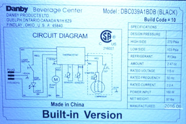
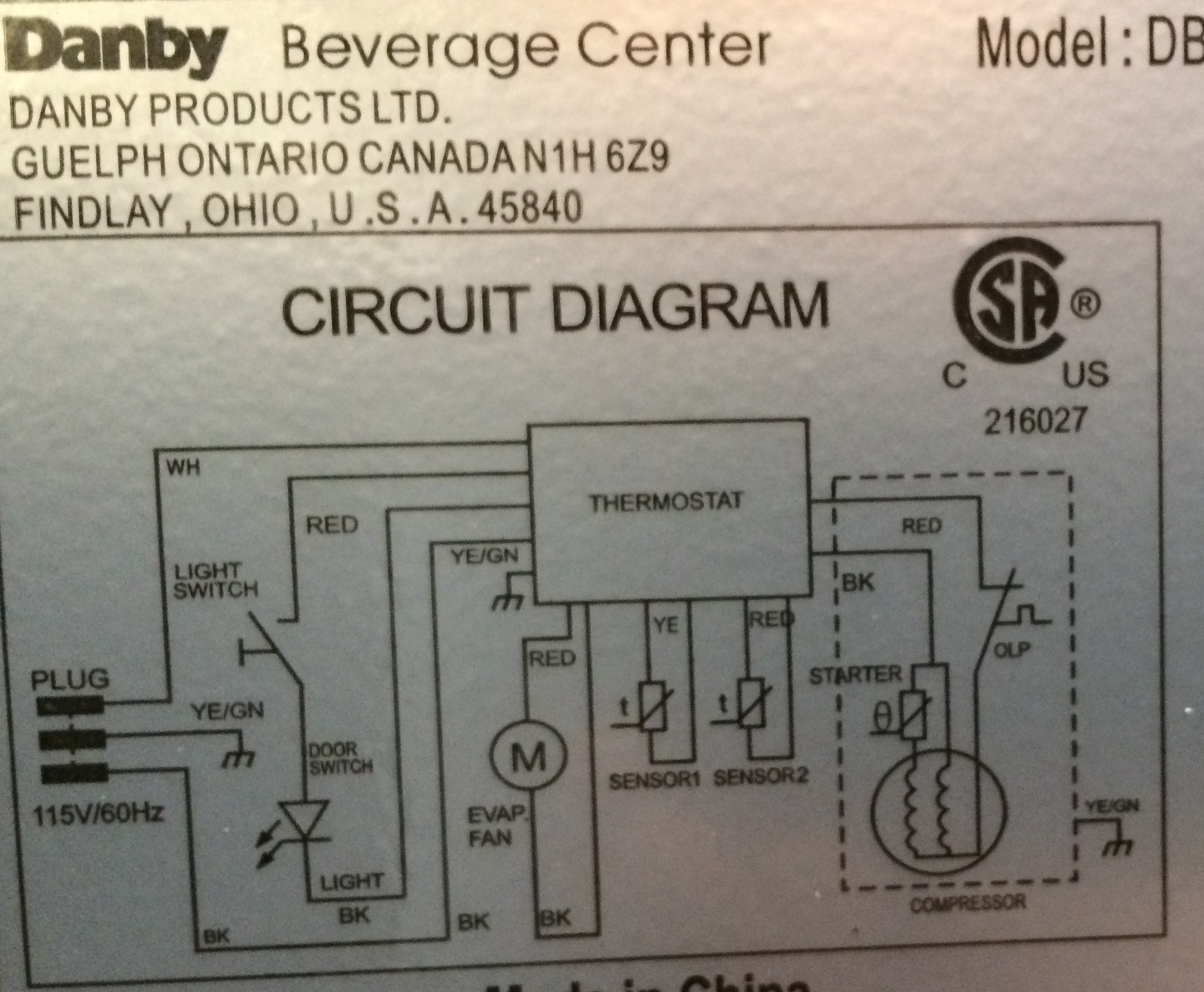
Checking the Danby wiring diagram I see white wire and black wire from the plug going to the Thermostat. From the Thermostat there are red wire and black wire going to the Compressor. I believe I need to cut the wires and then join the white with the red wire and the black with the black wire to cause the compressor to constantly run. Leave the other wires connected to the Thermostat alone. Then, plug in the Danby to the STC-1000 project box and insert the STC-1000 sensor into the Danby.

Does this sound valid?
 
Photo of the wiring diagram attached. Just wanted to ensure I described the wiring correctly.

DWD-2.jpg
 
Right.

I'm going to assume that Blk is always AC Line and Red is AC Neutral.
You might want to verify that before proceeding.

- The red and blk leads to the compressor need to be removed from the thermostat.
- Then the blk lead would go on the Cool relay switched output (with the other side of that relay wired to AC hot); and the red lead would connect to the supply Neutral wire.
- Next you need to disconnect the red and black Evap fan leads and parallel them with the like colored leads to the compressor.

The rest of the wires can be left in place, which should preserve things like interior lights, etc.
If the digital thermostat displays the interior temperature that should still work as well...

Cheers!
 
Right.
- Next you need to disconnect the red and black Evap fan leads and parallel them with the like colored leads to the compressor.
Cheers!

Why disconnect the Evap wires? The Evap motor runs when needed to eliminate moisture inside the beverage center. If I leave them connected as is then it will run when needed.

I agree with the black and red wires going to the compressor. I had the same idea after thinking about things for awhile.

When finished there are 2 plugs. The existing beverage center plug (that will now only control the lights and eval motor) and another new plug for the STC-1000.

Thoughts?

Thanks for the input.
 
"The Evap motor runs when needed"

An Evap fan blows air across the evaporator to distribute the "cold".

You've bypassed the oem thermostat, but propose leaving control of the evap fan to it anyway.
If you think the evap fan is still going to run at the proper time when your external controller is controlling the compressor, vaya con Dios...

Cheers!
 
So I recently bought a danbydkc644 used for cheap. I have have read a lot online about how the tower is warm and how the thermostat is not great. Im going to put a blower in to the tower and also want to bypass the thermostat and use a JohnsonA419 temp controller.

I just don't know where and what wires I should cut/put together to bypass the thermostat. Does anyone know? Thanks
 
Allegedly, this is the controller board for that fridge.

imageDisplay


At the top-right edge there's a receptacle for what appears to be the relay output to the compressor (and hopefully evap fan if there is one).
The corresponding plug carries Line and Neutral to the compressor, so you'd remove the plug and connect the Line wire to the STC-1000 Cool relay output and connect the Neutral to your neutral bus...

Cheers!

[edit] Potential gotcha: there is an evap fan, and it runs on 12V DC generated on the controller board (transformer and 3-terminal regulator). That complicates matters because the evap fan needs to run anytime the compressor is running, while your STC-1000 can only control one or the other.

The easiest work-around would be to add a 12V DC wall wart rated for 1 Amp to the switched/load side of your STC-1000 Cool relay, disconnect the 2-pin Fan plug from the white connector in the foreground of the controller board, and wire it to the output of the wall wart. You'll want to observe the correct polarity, of course...
 
Looking over the schematic again seems I simply need to cut the 2 wires (red and black) going to the compressor and insert the inkbird into the circuit. Doing so allows door switch, lights and fan to still work. The inkbird controls the cooling. Also, if I cut the red wires going to sensor2 I can wire these into the inkbird to monitor the temp.

Thoughts?

Re-read #9.
Then, Google "vaya con Dios"...
@day_trippr 's point is that proceeding as you propose is likely to be harmful to your system, for the reasons stated in his earlier posts.

https://www.spanishdict.com/guide/what-do-adios-and-vaya-con-dios-mean-in-english

Brew on :mug:
 
Looking over the schematic again seems I simply need to cut the 2 wires (red and black) going to the compressor and insert the inkbird into the circuit. Doing so allows door switch, lights and fan to still work. The inkbird controls the cooling. Also, if I cut the red wires going to sensor2 I can wire these into the inkbird to monitor the temp.

Thoughts?
I know this super old, but what did you end up doing?
 
Here's what I did without altering the fridge.

Find the thermostat / temperature probe inside the fridge. Mine was behind the back wall. It took 3 or 5 screws to undo, and it was obvious that it was the thermostat probe on a long wire. I think it might have been near the fan on the inside back wall. Sounds like you found two? Which is interesting. If your fridge has a temperature readout, you can try holding it in your hand for a minute and watching if the temperature rises on the display. If it does, then you should have the right one. If you're just going by the circuit diagram and noticing two sensors, then try finding the one inside the fridge. With any luck, it will be in the same spot - I think my beverage center is the same one, from the look of the front of it. You should find it behind the back wall, towards the bottom, in the center (left-to-right) near a screw. Don't bother opening up the whole display and control panel on the top inside - it's a pain to get back in and if I'm right then the sensor you need isn't there.

Now that you have the temperature probe, go to ebay and get something like this:
https://www.ebay.com/itm/5v-portabl...pad-carbon-fiber-heating-pad-Pip/173238963552

In case the link doesn't work in the future, it's a $0.99 5 volt (usb plug) carbon fiber hand warmer pad. Actually, the one I got a couple of years ago came as a two-pack, and the pad was smaller, I think. So I've got a backup in case something happens.

Put the hand warmer and temperature probe in a little box (battery box, film canister, etc. - whatever will fit them).

Find an old, low-power USB charger. The ones for the new devices can let a device draw 2 or 3 amps. I think the old one I found was rated for 500 mA. Not useful for modern phones, but perfect for this application.

Plug in the hand warmer on its own plug, and plug in the fridge to your inkbird. The warmer will fool the fridge into thinking it's very warm (100+ F), rendering its internal thermostat useless - it will be in "always on" mode trying to get colder but never getting there.

That's the solution I came up with for my beverage center, because whenever the inkbird would cut power it would reset itself to a setpoint of 50F or something like that. Again, it looks like you have the same model. Now it will get as cold as the inkbird will tell it to. The thermostat on the beverage center would only allow a setpoint of 40F at the coldest, but with this setup I got it down to freezing (accidentally) one time.
 
IMG_2256.JPG
IMG_2257.JPG
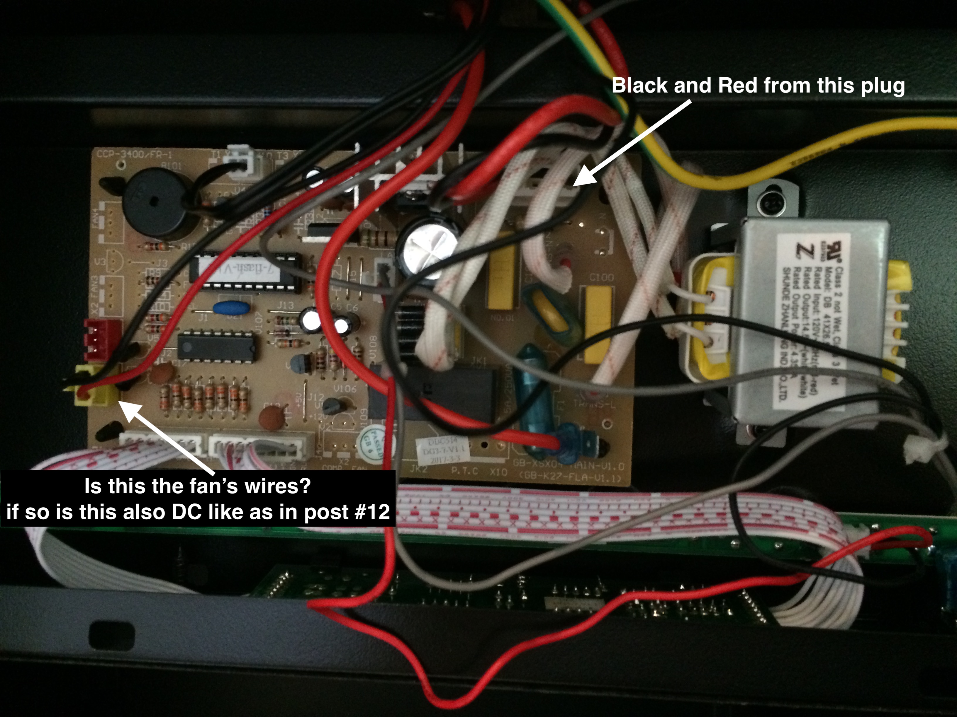
I have a question that pertains to this thread. I have a Dandy Beverage cooler (Model DBC039A1BDB). It has the same wire diagram as in post #6. The controller board appears similar but has some differences. (See attachments)

I would like to bypass the thermostat and leave the rest to function normally. Can someone point to the Black and Red wires that need to be cut and spliced together to bypass the thermostat? I only see two reds and one black wires. Is the fan DC as in earlier posts? I gotten myself confused and need input.

Thanks,
Phil
IMG_2256.JPG
IMG_2257.JPG
 
Sorry, no resolution to report. I was hoping that someone else had done this to save me some time. Oh well, next step is to trace wires with my multimeter but, I haven’t had time to conduct further expiration of the Danby wiring. I may not get back to this until later in the week. I live in the coastal region of North Carolina and will be spending the next couple of day prepping for Florence.

If I figure it out, I will be sure to post the resolution with pictures.

Phil
 
Back
Top