You are using an out of date browser. It may not display this or other websites correctly.
You should upgrade or use an alternative browser.
You should upgrade or use an alternative browser.
Two 5500 watt 240v heating elements not heating up.
- Thread starter LoganBrew
- Start date

Help Support Homebrew Talk:
This site may earn a commission from merchant affiliate
links, including eBay, Amazon, and others.
I don't think so. Two elements on should heat just fine until the breaker trips.i havent switched my 40amp breaker with a 50 yet, could there be some sort of safety in the system that if there's not enough power that the elements just wont turn on?
Brew on

Now that you have a multimeter, set it for AC volts, and at least a 250V full scale, then check the power at the 240V outlet you are using. Assuming you have a 14-50 receptacle for an outlet:

If you test between the left and right slots, you should read ~240V. Left to top or bottom should read ~120V, Right to top or bottom should read ~120V, and top to bottom should read ~0V. If any of these readings are way off, then your outlet is wired incorrectly.
Brew on
If you test between the left and right slots, you should read ~240V. Left to top or bottom should read ~120V, Right to top or bottom should read ~120V, and top to bottom should read ~0V. If any of these readings are way off, then your outlet is wired incorrectly.
Brew on

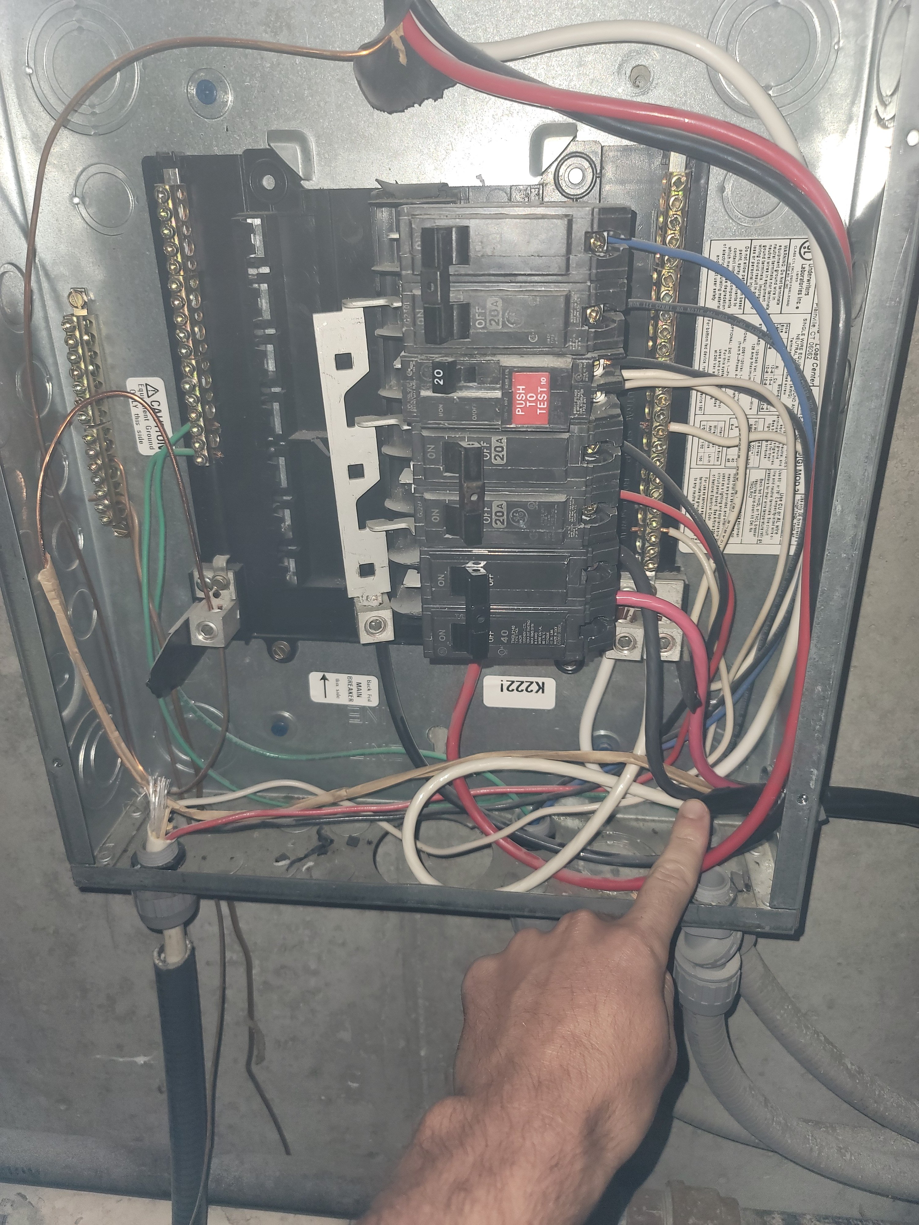
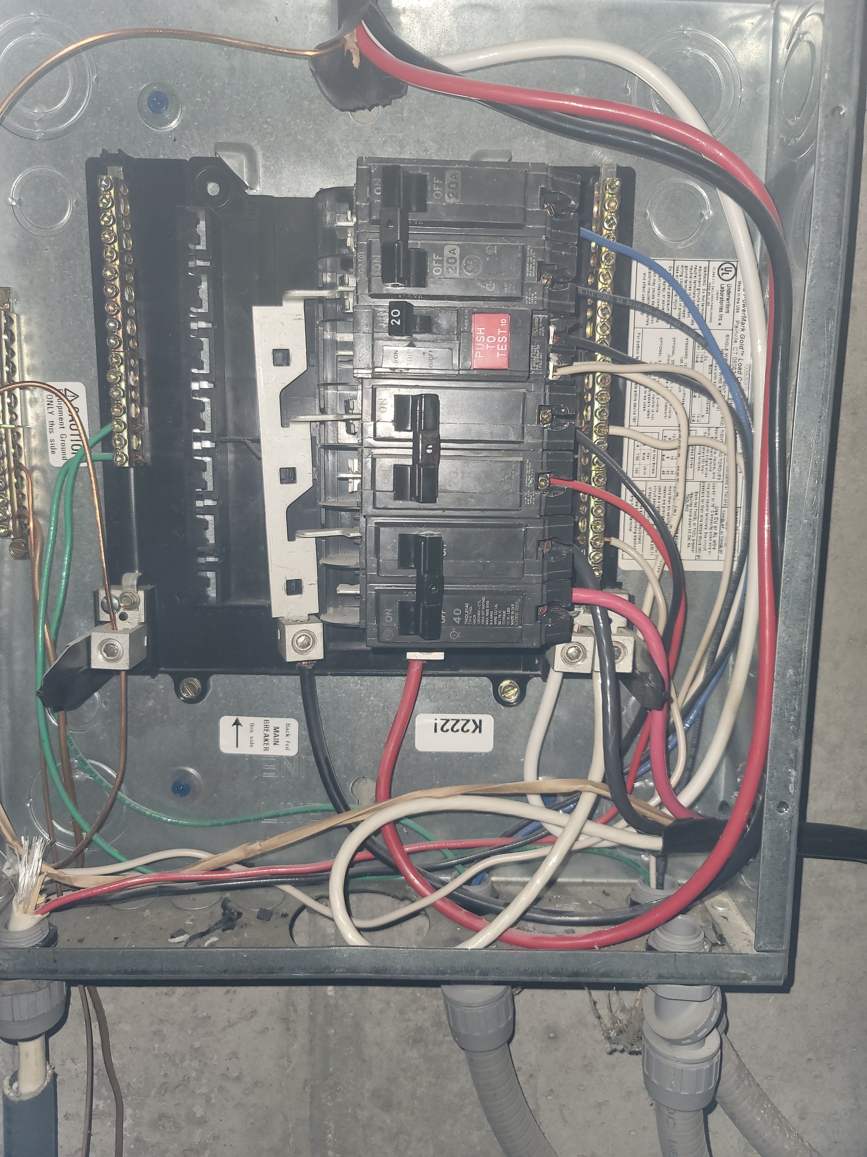
That left main bus bar in the breaker panel looks like it has broken loose of its moorings. It may not be making contact with the back of the breaker. This could be the cause of your problem. I'd look into this first. The breaker itself seems to be connected correctly. But, this is not a GFCI breaker, and you really want GFCI for your own protection. Regular breakers just protect the wiring from overload - they do nothing to protect you.This is our wire set up, we aren't plugging the pid into an outlet they are I just wired directly in
The wire connections at the "outlet" box look like they are correct. However, it is my understanding that the National Electrical Code (NEC) no longer allows appliances to be hard wired to the structure wiring. Technically what you are doing is a "no-no."
Brew on


![Craft A Brew - Safale BE-256 Yeast - Fermentis - Belgian Ale Dry Yeast - For Belgian & Strong Ales - Ingredients for Home Brewing - Beer Making Supplies - [3 Pack]](https://m.media-amazon.com/images/I/51bcKEwQmWL._SL500_.jpg)


$479.00
$559.00
EdgeStar KC1000SS Craft Brew Kegerator for 1/6 Barrel and Cornelius Kegs
Amazon.com


$53.24
1pc Hose Barb/MFL 1.5" Tri Clamp to Ball Lock Post Liquid Gas Homebrew Kegging Fermentation Parts Brewer Hardware SUS304(Liquid Hose Barb)
Guangshui Weilu You Trading Co., Ltd


$20.94
$29.99
The Brew Your Own Big Book of Clone Recipes: Featuring 300 Homebrew Recipes from Your Favorite Breweries
Amazon.com


$10.99 ($31.16 / Ounce)
Hornindal Kveik Yeast for Homebrewing - Mead, Cider, Wine, Beer - 10g Packet - Saccharomyces Cerevisiae - Sold by Shadowhive.com
Shadowhive


$58.16
HUIZHUGS Brewing Equipment Keg Ball Lock Faucet 30cm Reinforced Silicone Hose Secondary Fermentation Homebrew Kegging Brewing Equipment
xiangshuizhenzhanglingfengshop


$7.79 ($7.79 / Count)
Craft A Brew - LalBrew Voss™ - Kveik Ale Yeast - For Craft Lagers - Ingredients for Home Brewing - Beer Making Supplies - (1 Pack)
Craft a Brew


$53.24
1pc Hose Barb/MFL 1.5" Tri Clamp to Ball Lock Post Liquid Gas Homebrew Kegging Fermentation Parts Brewer Hardware SUS304(Liquid Hose Barb)
yunchengshiyanhuqucuichendianzishangwuyouxiangongsi


$22.00 ($623.23 / Ounce)
AMZLMPKNTW Ball Lock Sample Faucet 30cm Reinforced Silicone Hose Secondary Fermentation Homebrew Kegging joyful
无为中南商贸有限公司


$33.99 ($17.00 / Count)
$41.99 ($21.00 / Count)
2 Pack 1 Gallon Large Fermentation Jars with 3 Airlocks and 2 SCREW Lids(100% Airtight Heavy Duty Lid w Silicone) - Wide Mouth Glass Jars w Scale Mark - Pickle Jars for Sauerkraut, Sourdough Starter
Qianfenie Direct


$176.97
1pc Commercial Keg Manifold 2" Tri Clamp,Ball Lock Tapping Head,Pressure Gauge/Adjustable PRV for Kegging,Fermentation Control
hanhanbaihuoxiaoshoudian


- Joined
- Jul 12, 2017
- Messages
- 489
- Reaction score
- 422
What is the Awg of that wire in breaker box? Looks like #10 Gauge THHN Copper Stranded Wire, if so that is not going to cut it. You could put a spa panel where you hardwired into the wall, or just take the breaker out of a spa panel and put it in the breaker box( as others have stated a 50 amp minimum but a 60 amp would be better) but wire size is in question. None of this is related to why your elements aren't working but this also would need addressed.
@doug293cz you were right we fiddled with it for a bit and got it all hooked up right. Now the elements are heating up!! This is just a temporary setup in the garage to make sure everything is working. we will be moving into a commercial location this summer and I'm sure we will have to get everything inspected when that happens. Thank you guys for all your input and help!!
That left main bus bar in the breaker panel looks like it has broken loose of its moorings. It may not be making contact with the back of the breaker. This could be the cause of your problem. I'd look into this first. The breaker itself seems to be connected correctly. But, this is not a GFCI breaker, and you really want GFCI for your own protection. Regular breakers just protect the wiring from overload - they do nothing to protect you.
The wire connections at the "outlet" box look like they are correct. However, it is my understanding that the National Electrical Code (NEC) no longer allows appliances to be hard wired to the structure wiring. Technically what you are doing is a "no-no."
Brew on
Once that portable cord is hard wired to the building, it falls under the purview of the electrical inspector. Putting a receptacle in the box and a plug on the cable is the way to do it legally.
Are the relays actually contactors and not mechanical relays? The later can't handle the fast switching of a digital controller. Not sure if they aren't heating at all or just getting warm.
Contactors ARE mechanical relays. And in this (and almost every other controller) design the element isolation contactors are not being driven by the PLC's PID. The PID controls switching of the SSRs, which are what actually modulate power to the elements. The contactors/relays are used to enable/disable power to the elements by providing galvanic isolation.Are the relays actually contactors and not mechanical relays? The later can't handle the fast switching of a digital controller. Not sure if they aren't heating at all or just getting warm.
Also, the OP has diagnosed the issue as faulty structure wiring in the circuit that was supposed to provide power to the controller. Essentially the controller wasn't completely "plugged in."
Brew on
@doug293cz very impressive on how you reverse engineered the system, came up with the wiring diagram, and the troubleshooting that you did on resolving the issue.
I'm amazed sir.
I'm amazed sir.
Thanks. I like to help where I can.@doug293cz very impressive on how you reverse engineered the system, came up with the wiring diagram, and the troubleshooting that you did on resolving the issue.
I'm amazed sir.
Brew on
And The wizard strikes again ! Nice job DougThat left main bus bar in the breaker panel looks like it has broken loose of its moorings. It may not be making contact with the back of the breaker. This could be the cause of your problem. I'd look into this first. The breaker itself seems to be connected correctly. But, this is not a GFCI breaker, and you really want GFCI for your own protection. Regular breakers just protect the wiring from overload - they do nothing to protect you.
The wire connections at the "outlet" box look like they are correct. However, it is my understanding that the National Electrical Code (NEC) no longer allows appliances to be hard wired to the structure wiring. Technically what you are doing is a "no-no."
Brew on

Are the relays actually contactors and not mechanical relays? The later can't handle the fast switching of a digital controller. Not sure if they aren't heating at all or just getting warm.
Contactors are mechanical relays. The Solid State Relays (SSRS) are the fast switching ones. Both are in that box. SSRs are under the control of the PID or micro computer and the mechanical relays are under the control of the brewer. Oops.. I forgot to refresh the page and have been redundant.
RufusBrewer
Well-Known Member
Terminology can be confusing. A conventional relay uses a coil that when energized creates a magnetic field that pulls one of more electrical contacts closed. These contacts might have a normally closed and normally open and a common combination terminals.
A contractor is very similar to a relay. Both use a coil that pulls the switch contacts together. I have never seen a reliable definition of what makes a contactor different than a conventional relay. From what I can tell, contractors tend to be for higher power and mostly normally open.
Key point is a relay and contracter both use coils and a mechanical switch that you can see and hear.
Solid state relays use transistors other solid state elements to switch their signals. They have no moving parts. The switching element is "fast". That means you can switch it on and off many times a second. (relays you do not want to turn them on and off very often)
Solid state relays the switch section has only two terminals, they are either On/closed (passing current) or Off/open (not passing current)
Solid state relays have a wide range of input signal. A few volts up to about 30 volts DC. Depends on relay design and specifications.
One tricky part about SSR, you cannot put a meter on the switch terminals, apply a signal to the input and observe the switch close. A meter across the switch terminals will not show a change on the meter. You must put an active load, to see the observe the relay change state.
With solid state relays, cooling and heat management is an issue. They can generate heat when used, and that heat needs to be dissapted.
Last edited:
Similar threads
- Replies
- 20
- Views
- 965
- Replies
- 25
- Views
- 1K
- Replies
- 6
- Views
- 927
