
Hey all, I'm hoping for a bit of advice troubleshooting my new RIMS controller. It's made up of a MyPin TA4 PID, 40amp Fotek SSR and an RTD.
It's all wired up, and here's the behaviour:
My interpretation (with the assistance of a much more capable friend) is that the SSR is likely functional, but there's a setup or wiring issue with the PID. Does anyone have any thoughts? Thanks!
It's all wired up, and here's the behaviour:
- Probe reports accurate temperature to PID
- PID seems to accept new set points
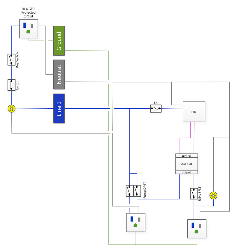
- If power switches (Pump interlock and Element) are on, element is always on
- Disconnecting the signal voltage lines from the PID turns element off; shorting the two leads together (shorting the control terminals on the SSR) turns element on
- Swapping the control leads on the SSR does not appear to change the situation
My interpretation (with the assistance of a much more capable friend) is that the SSR is likely functional, but there's a setup or wiring issue with the PID. Does anyone have any thoughts? Thanks!
 Thanks for your help.
