geologyguy
Well-Known Member
So I am wanting to make this set up. I spent time on it and seems good to me but what do you all think? I would love the input to see if I forgot something? Do I even need the stirrer?


") .
.

Thanks for the info. It got me thinking more. I really appreciate it. So i redesigned it a little. What do you think? Would this work for a 3.5 bbl system? I am more concerned with the mast tun. Would this work or would the wort be scorched?
![Craft A Brew - Safale S-04 Dry Yeast - Fermentis - English Ale Dry Yeast - For English and American Ales and Hard Apple Ciders - Ingredients for Home Brewing - Beer Making Supplies - [1 Pack]](https://m.media-amazon.com/images/I/41fVGNh6JfL._SL500_.jpg)


Also,
Heres a link to my P&ID. I'm not a ME or ChemE but here ya go.
With a drawing like this you could fool just about anyone.
1. I would relocate TT02 to be at the output of the HLT ball valve. You want to control the temperature of the water you are delivering to the MLT for mash in and sparge. This is same as how Kal does it and I agree it's the best way, and its easy to pipe.
2. It looks like you have more valves than you need. Can you explain the intent of each valve here?
3. You mentioned hard piping. What's your CIP plan here?
. The two manual valves at the pump outlets are for flow control. The manual valves on the vessels are for monetary concerns! If you can help me on cutting down on valves I am down for that!!!#2 - Now that I see your equipment phases I think you've put your valves in the correct spots and the functions make sense for what you're doing.
#3 - I don't think spray balls are the right solution for this. Those are more for tanks. You also need really high pressure (e.g. 100 PSI) to operate them correctly. The home brew pumps we use are under 10 PSI. I have some more ideas on the topic but I'll have to elaborate more later. The short version is i wouldn't make it an after thought because you can make it integral to your piping design.
I will be okay with hoses indefinitely #3 Oh, I mean that hard plumbing isn't coming in for years. I plan on working out CIP before I pipe in. And after looking at your PID I might just borrow your ideas
2. Recirculating BK chilling - This chills the entire volume together so it makes it possible to do things like 170F steeps. Its also very easy to chill. Ground water this time of year is about 40F so i just let it rip for about 5 minutes to get down to ~110 (and the temp out of my plate chiller is reading about 45), then divert to fermenters and run it all out. During the warmer months i'm going to use my MLT as an ice water tank and recirculate the cool water back to the ice bath since it'll still be colder than tap water.
.
- I meant to put it there. But I revised too fast!
- More valves? I tried to be consitent with the flow path following kals diagram. The flow paths and sequence can be seen HERE
- I haven't gone through with it. This is a contingency once I get all my vessels and panels done and have settled in (years from now). I would love any ideas on CIP. Im thinking spray balls to each kettle, then just flush everything out to a drain via the main line down where the pumps are. Then I could flush the pumps with hot water.
Nice man. Looks like you have it all figured out. I think your diagrams will help me out. What did you use for your electronics? Also what program you use to draw your diagrams?
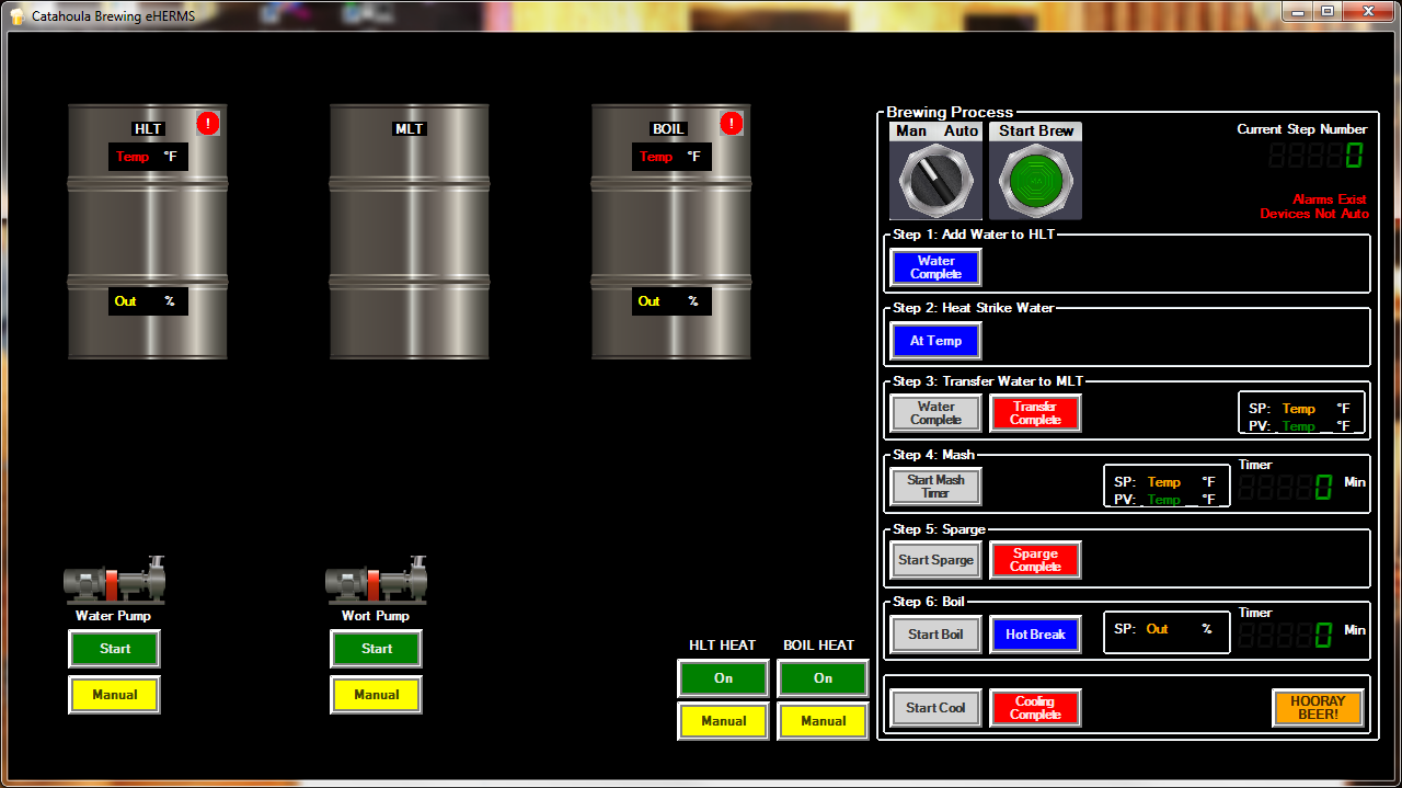
.Would you mind posting some pics of your HMI?HMI is done through AdvancedHMI (free software). I am about 95% done with the control panels.