OP
OP
jsguitar
Well-Known Member
Not Zacc, but it looks like he drilled holes for four panel mount fuse holders like I did and he has one installed in the back panel already.

Ok. I hope you are ready for this as it becomes a little more complicated. BTW, I totally agree that an indicator light is needed to ensure some additional level of comfort with the system. The lamp will indicate if the switch is powering either element circuit.
The double pole - double throw - center off - switch needs to be changed out to a - Triple Pole - Double Throw - Center Off - switch in order to accommodate the indicator lamp.
Mouser PN 633-S33-RO (click it).
The indicator lamp shown is this one from
grainger.com PN 1XWL6 (click it). {BTW - the lamp is actually Amber in color. If you want a green one it's pn 1XWL4. Red is pn 1XWL1}
Now the new diagram (click on the image for a full scale drawing printable on tabloid paper 11" x 17")

Where else are you going to get a custom diagram.
I really enjoy the mind jumps I go through to come up with the plans.
I sure hope this helps you.
Best regards,
P-J
![Craft A Brew - Safale S-04 Dry Yeast - Fermentis - English Ale Dry Yeast - For English and American Ales and Hard Apple Ciders - Ingredients for Home Brewing - Beer Making Supplies - [1 Pack]](https://m.media-amazon.com/images/I/41fVGNh6JfL._SL500_.jpg)


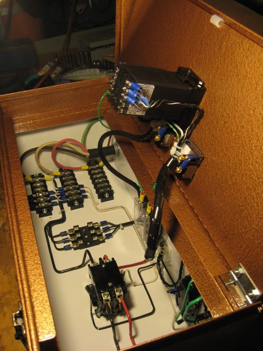
Ok, I got it put together!
I can't test it fully yet for a couple of reasons. I had a leak in a sight glass and am waiting on the replacement for that and I also damaged my element in the boil kettle because my hole was just a tiny bit too small. It got stuck so I ended up using a piece of wood and a hammer to get it out. It looked liked I knocked the base loose so I ordered a replacement.
I also have to clean and organize my basement in order to make space in the laundry room. Not looking forward to that.
I tested it with my multimeter a lot along the way, checking continuity at every point before powering it up and checking voltage at the outlets once it was powered. I'll need to hook up the rtd probe later and figure out the pid to check everything, but at this point everything seems perfect.
I had some small tragedies with the hole saw. I'm an idiot with a hole saw apparently and it took me a while to realize I needed to make a jig by cutting a hole in a piece of wood to guide the thing. I had only drilled a pilot hole and clamped a piece of wood behind it at first. I broke the first pilot bit in the mandrel trying to make a hole for the GFCI outlet....it snapped and the saw jumped. I didn't learn. I then broke another I had, and then bent drill bits I used as guides.I finally got it cut and then proceeded to destroy the back of the control panel! I finally got it right after that with the jig and it was a breeze.
Anyway, you'll see that I filed, sanded, and painted the tragic gouges in the GFCI and control panel. For the GFCI, I used the gray primer and silver hammered metal paint that I was using for the element boxes. For the control panel I used a flat black 2000 degree auto exhaust paint. It worked well and I used it on the front too to clean up some smaller scratches and nicks.
Disclaimer: I'm not an electrician and don't even play one on TV so do not use my electrical work as a guide. This is dangerous! Consult an electrician!!!
Anyway, with that out of the way lots of pictures to load.
Pic 1: hole saw tragedy on back of control panel
Pic 2: damaged bits
Pic 3: jig....finally!
Pic 4: filed and sanded gouges out
Pic 5: final back of panel after painting
More pics in next post.


Take a look at what is available at Harbor Freight - http://www.harborfreight.com/knockout-punch-kit-91201.htmlWhew, Greenlee punches are too rich for my all aluminum kettle blood. I think I'm gonna buy my 22.5mm punch for the buttons and will get a 1 1/4" and 1 1/2" hole saws.
I cannot make judgment on your situation.Would you recommend those punches? I'm scared of em. They get pretty bad reviews. I already have both of those step bits
I figure since I have a drill press the hole saws are viable. I was gonna grab Dewalts.(plus I have some amazon credit so I can get em for like 10 bucks shipped)
I feel like the holesaws(with drill press) will produce much cleaner holes than step bits. I just like the one punch I listed because its like the perfect size for the job.
Will those HF punches fit the Estop and switches?
http://www.automationdirect.com/adc...adc.falcon.search.SearchFormCtrl&TxnNumber=-1
Now I'm looking into what wire I need. What gauge wire should I use inside the GFI box? Inside the control panel what connections need 10AWG and what connections need 14AWG. (Can I just buy a spool of 12 AWG?)


I was just thinking about something on mine. All of my controls are on the lid which is not hinged. That's going to make it hard to open it up and set the list somewhere safe. Would it be possible to create a wire harness so I can remove the lid? Anyone have any experience with something like this? Is it hard to do?