• Please visit and share your knowledge at our sister communities:
  • If you have not, please join our official Homebrewing Facebook Group!

    Homebrewing Facebook Group

Stc-1000+

Homebrew Talk

Help Support Homebrew Talk:

This site may earn a commission from merchant affiliate links, including eBay, Amazon, and others.
Do you have any links on how to do this. I've been on-and-off looking for a dummies version of how to replace the thermostat on my refrigerator with an STC1000+ and avoid having a box duct taped to the side of my ferm fridge.

Here is how I did my fridge conversion. You should be able to do something similar with other fridges. To find out what wires you need to connect you could unplug the fridge, take apart the temp adjuster and then use a multimeter to check continuity between the temp adjuster and the wall plug. You should just have to find hot and neutral. Then find the one that connects to the compressor. Mine happened to be red to the compressor, blue was neutral and brown was hot. I then tested my theory by connecting the hot (brown) wire to the compressor (red) wire and plugged the fridge on. The compressor kicked in and i was off to the races.

YMMV but Good luck.
 
Do you have any links on how to do this. I've been on-and-off looking for a dummies version of how to replace the thermostat on my refrigerator with an STC1000+ and avoid having a box duct taped to the side of my ferm fridge.

No, but I'm sure there is something on line.

It's not difficult. You just want to disconnect the internal thermostat and run the power to the controller. Each unit will be slightly different due to the location of the thermostat and how the wires are routed through the unit. Mine is an expensive one where everything is replaceable vs being installed through walls and insulated over...etc.

Make sure the stc can handle the amps for the chamber you're using. I believe the stc is rated for 15 amps at 120v, so shouldn't be an issue for most fridges.

*edit* there you go. I see someone got you some info above. It's not hard, so don't be intimidated. Good luck!
 
Simple question, the user manual for my stc before flashing gave range as -50 to 99degrees C . I suspect that was the case for all A400_P's.I noticed the user manual for the 1000+ states -40 C to 140 degrees C .does this remarkable firmware change, extend the range of the controller? Kind of irrelevant but seems a bonus.
 
Well, the range needs to be taken with a grain of salt. The NTC temperature-reaistance curve is very non-linear, so while you can squeeze some more range out of the ADC, accuracy gets worse the further you get from +25C.
I think the main reason they state 99 degrees in the stc manual, is that it only has 3 digits and one is used for decimal. I solve it by dropping the decimal when I need all three digits, but I guess they didn't want to mess with that.
 
Alpha:
I know that you have focused on the STC-1000+ controller, but have you seen the ITC controllers from Inkbird? Didn't know if these controllers were programmable. They are similar to the STC, but in Fahrenheit instead of Celsius. If they were programmable, would this allow for more features since I know the code is limited?

Just a thought.

Links: ITC-1000
ITC-2000
 
Last edited:
@Perzellbrewing:
Yes, I've seen them. What makes the STC-1000 (A400_P version that is) so suitable, is that it has a PIC microcontroller, so it has tools (compilers et.c.) and datasheets availiable.
I don't know anything about these controllers, it would probably be possible (as they are programmed at some point during manufacturing), but is it practically doable?
What do these offer that the STC don't? Seems like very much the same thing, except they are preprogrammed for F. I really don't have much incentive to look into those, as it will probably be a lot of work (if even doable) for little or no benefits.
If you get one, please do let me know what MCU is used. If it is something relatively open (i.e. has the needed documentation) and has better specs than the PIC16F1828, then it might be interesting.
 
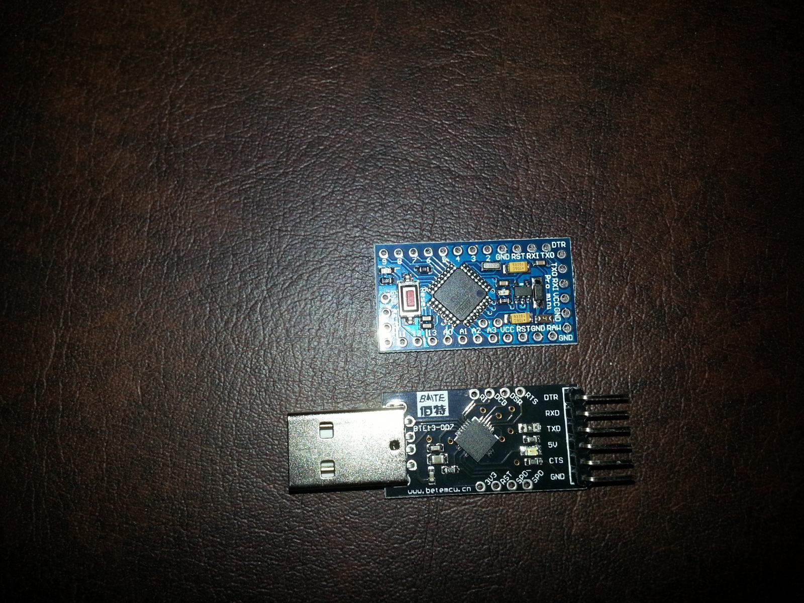
I'm trying to build a arduino pro mini set up like alphaomega and flomaster did (post 1532?). I ordered off ebay from china and of course got a few components that look a bit different than what I was expecting. I think it will still work but I'm struggling with aligning the usb to arduino as the pins aren't in the same position or have same labels. Tried a few google searches but since it is a "no name unit" I can't find anything.

Any advice would be appreciated. I've attached an image of the two components. I think it came out clear enough.

If these are totally wrong/incompatible I'll probably just scrap it. Was looking for an easier way to be able to flash update my controller. But I can open my box I suppose if and when I need to.

Thanks!
Brian

20150130_145128.jpg
 
I'm trying to build a arduino pro mini set up like alphaomega and flomaster did (post 1532?). I ordered off ebay from china and of course got a few components that look a bit different than what I was expecting. I think it will still work but I'm struggling with aligning the usb to arduino as the pins aren't in the same position or have same labels. Tried a few google searches but since it is a "no name unit" I can't find anything.

Any advice would be appreciated. I've attached an image of the two components. I think it came out clear enough.

If these are totally wrong/incompatible I'll probably just scrap it. Was looking for an easier way to be able to flash update my controller. But I can open my box I suppose if and when I need to.

Thanks!
Brian

I think you will need to remove the pin labeled 'cts', other than that, it looks like the pins you need line up fine (dtr-dtr, txd-rxd, rxd-txd, vcc-5v and gnd-gnd). But before you do anything permanent see if you can test if it will work. You can for example bend just the cts pin straight, plug in the usb and fire up arduino ide. Make sure you find the com port, if you do, you can try to upload a sketch by simply attaching the arduino to the pins and press slightly to make the connection. If you can upload like this, you are good to go. Remove the pin and solder it up.

Edit: By press slightly, I mean that your arduino will be pointing up (vertically), put some pressure on the top of it (horisontally) so that it wants to bend against the pins. This way you will have a good connection (I've done this myself a couple of times to upload a sketch without having to solder in the connector on the arduino).

That's right, tx and rx and reversed

Thanks guys. I bent the CTS out of the way. I've tried it now the exact alignment Pro-Mini -> USB; DTR->DTR, TXD->RXD; RXI->TXD; VCC->5v; Open->Open; GND->GND. I also tried with DTR->TXD and TXD->TXD.

Each time I get the error message:
Done Uploading
Binary sketch size: 29,986 bytes (of a 30,720 byte maximum)
avrdude: stk500_getsync(): not in sync: resp=0x00

Google informs me this is an indication that my PC is not communicating with my arduino.

USB has a red light when I plug into pc and when I hook pro mini to USB I get a red light as well a blinking red light near the reset button.

When plugged up to the the USB and put on a multimeter with VCC and GND I am reading 5V and appear to have good continuity between USB and Pro Mini for all connections.

I tried selecting a few different ATmega328 boards from Arduino IDE. Same results other than it informed me I didn't have enough space for the sketch on a few of them.

Any other ideas?

Edit - The IDE is only showing COM3. I can see my pc is recognizing the USB port when I plug it in, does not specify a COM# nor does it recognize the arduino when connected to the USB.
 
It's the com port setting, go to device manager and make sure its driver is installed, you may have to go to their site. Then in pic prog make sure that the com port being used in device manager is selected. Had the same issue today had to reboot to finally get comport 5 to display which is what I could see in device manager
 
@Smithabusa
#lifesaver

Downloaded and imstalled a cp2101 driver. Successfully uploaded sketch. Did not get a chance to flash my STC, but will give it a go lster today.

Appreciate the help.
 
Anyone able to point me in the direction of a good size enclosure for this? Prefer something that is well sized, not an electrical enclosure box. I have access to a machine shop so fabrication is no problem and would prefer to order from digikey/mcmaster/mouser since my co. has accounts with them.
 
Anyone able to point me in the direction of a good size enclosure for this? Prefer something that is well sized, not an electrical enclosure box. I have access to a machine shop so fabrication is no problem and would prefer to order from digikey/mcmaster/mouser since my co. has accounts with them.

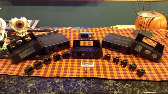
I sell them already machined for my DIY kits if you are interested, its a polycase, I think they only sell direct, not through other distributors.

polycase.jpg
 
You can buy those enclosures at any RadioShack but they don't come pre-machined
 
Ok, time for an update.
I've been working on the next version. Nothing really major, but I have cleaned up the code a bit more and made a few technical improvements.
Biggest actual change is that I have dropped one profile and added an extra parameter at the end of each profile (nr or next runmode), it can be set to profile 0-4, th or off. So when the profile completes it either starts another (or the same) profile, switches to thermostat mode (with the last known setpoint) or switches to soft off mode.
This makes profiles more versatile, but might not add a lot usage for fermentation.
I have yet to update documentation and I also plan to include the newer profile editor/hex generator (but I need to update that aswell now).
Note that eeprom layout also has changed.
I'd like feedback / test results before I make a release, so please try it out (it is located in the work branch)
Oh, and I you're one of the brave few, please try and keep an eye on the timing (I have switched to a 16 bit timer to generate a better 16 Hz clock, so a minute should be closer to a minute and hopefully an hour should still be pretty close to an hour).

I've also been working on a firmware to control a one vessel brewing system (like a brewmeister type setup or even biab). It is still pretty early on, but it is shaping up quite nicely. It is mainly for my own purposes, but you can check it out if you want to. It is currently located here.

Cheers!
 
I've also been working on a firmware to control a one vessel brewing system (like a brewmeister type setup or even biab). It is still pretty early on, but it is shaping up quite nicely. It is mainly for my own purposes, but you can check it out if you want to. It is currently located here.

Cheers!

This ^ is awesome, I was going to try to rig something up so I could set a timer and wake up to hot strike water, looks like I can just set a delay before it starts the profile.

Quick question about flashing the controllers. Do you need to pull the nMCLR line down while flashing? We have SILabs debug adapters at work and I was thinking of trying to flash one with that.

Thanks for all your work on this.

-Ryan
 
Went to use the web profile editor yesterday and it wouldn't work. Is it being worked on? No biggy, just a nice way to verify my settings!

Thanks!
Casey B.
 
I looked around and didn't see this, so....

I have the STC-1000+ hooked up, running in thermostat mode, and although the setpoint (SP) in the settings is set to 34.2, the unit is constantly in cooling mode (indicator light on the top left). I am uncertain what is going on, and can't get it to shut the freezer off. The temperature was showing 26 degrees, and I have had to unplug the freezer to get it to stop.

My Kolsch will appreciate whatever help and insight you can provide.

T
 
Went to use the web profile editor yesterday and it wouldn't work. Is it being worked on? No biggy, just a nice way to verify my settings!

Thanks!
Casey B.

It might be my own fault, for putting stuff up on my drive and generating a bad short URL at some point. Ti should be ok if you use this link.
http://goo.gl/z1KEoi

I looked around and didn't see this, so....

I have the STC-1000+ hooked up, running in thermostat mode, and although the setpoint (SP) in the settings is set to 34.2, the unit is constantly in cooling mode (indicator light on the top left). I am uncertain what is going on, and can't get it to shut the freezer off. The temperature was showing 26 degrees, and I have had to unplug the freezer to get it to stop.

My Kolsch will appreciate whatever help and insight you can provide.

T

Odd. I assue it has been working properly before? And it is not a matter of flashing the fareheit version when expecting celsius readout? What firmware version are you using?
When you say temp readout of 26, that is on the STC? Did is change, or was the value 'frozen'?
I seem to recall someone experiencing a hung controller at some point, it was ok after he powercycled it. Seems weird to me, as it uses a watchdog timer, that should reset the unit if it becomes unresponsive.


Alpha:

No, it has not been working. This is the initial setup. All temps are showing F, and I will try and figure out the firmware version - I got this one pre-flashed.

WRT the temp showing 26, it was not frozen, it was still dropping down - I unplugged the freezer to keep from inadvertently creating an ice beer. I powercycled the controller this morning; I will try and let it cool again this evening after work.
 
Ok.
If the temp reading is updating, then it is pretty safe to assume it has not locked up. Double check settings (not that I think there is anything wrong, but hysteresis for example could be a thing).
Well, if it wasn't' functional "before" there is of course the off chance that either the controller and/or flashing is bad. But I wouldn't jump to that conclusion, do some 'bech testing' (that is not on actual beer)...

Cheers!
//mats
 
Thanks again - I plan to keep a close eye on it for a while. I also reset a bunch of the settings back to default, but... who knows?
 
Also make sure you aren't looking at the secondary probe readout, even with it not turned on you can see a value, and it won't match the primary temp sensor, I've seen this cause confusion before. Pushing the power button will cycle between temp sensor 1 and 2
 
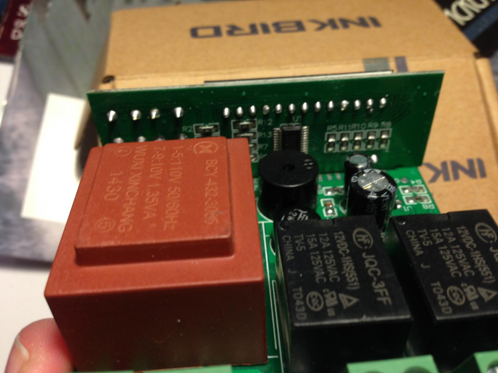
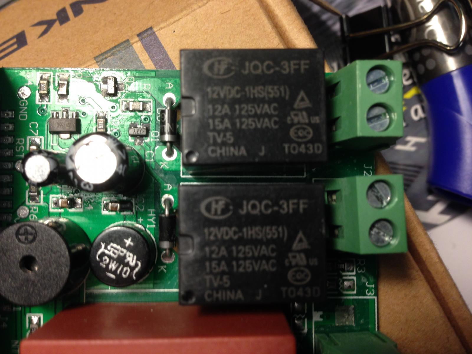
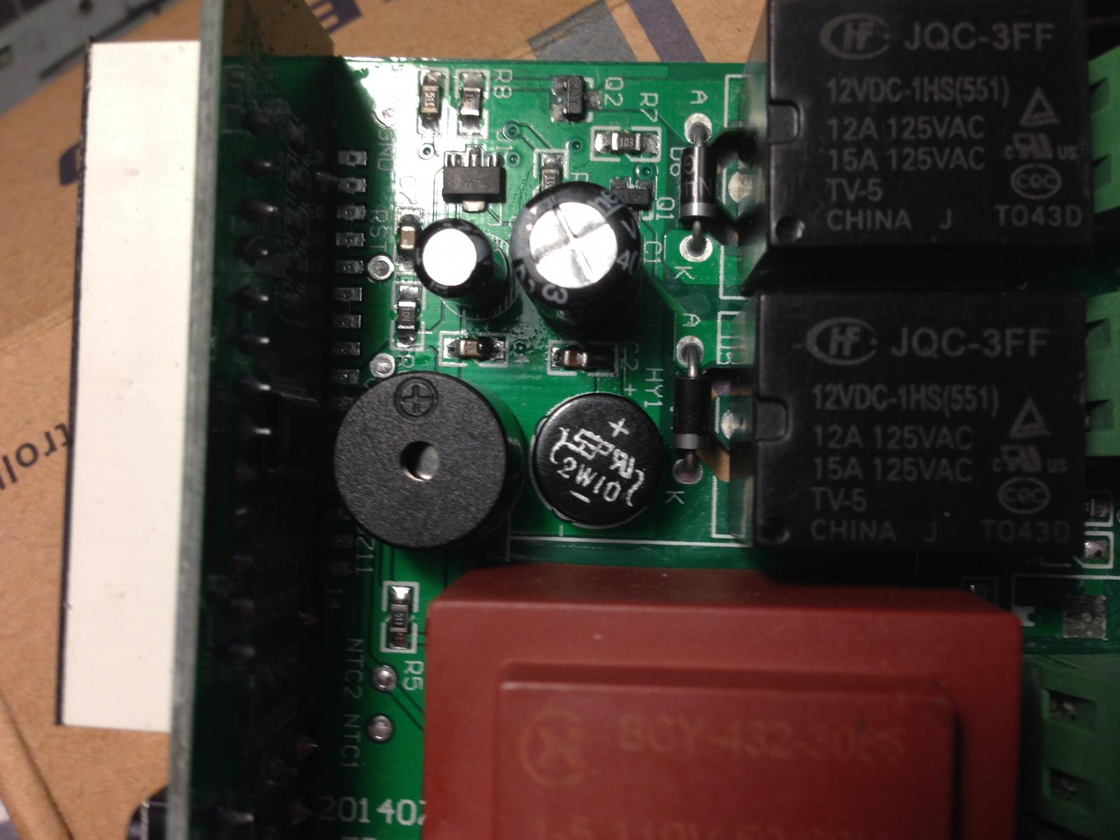
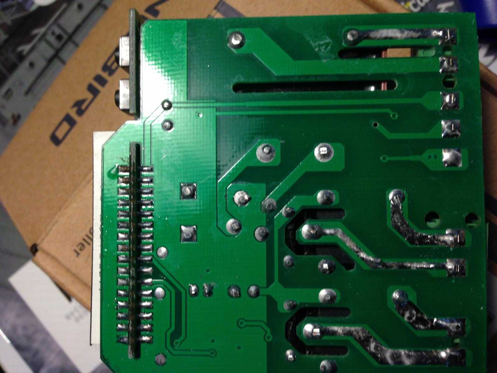
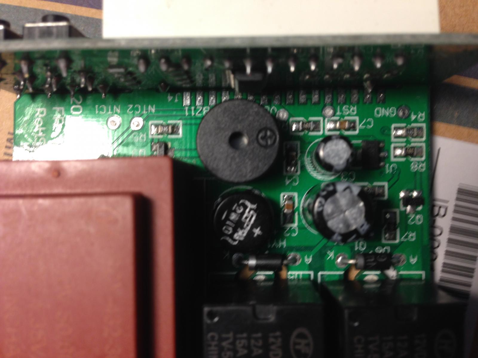
I recently purchase a ITC-1000 for $15.00 on ebay it appears to be identical please see the attached pictures. Let me know if you think the firmware could be loaded on this controller.

IMG_2450.jpg


IMG_2445.jpg


IMG_2446.jpg


IMG_2447.jpg


IMG_2448.jpg


IMG_2449.jpg
 
Here's a summary of post regarding your "ITC-1000" unit.

Posts asking if these units can be flashed with STC-1000+ firmware:
I recently purchase a ITC-1000 for $15.00 on ebay it appears to be identical please see the attached pictures. Let me know if you think the firmware could be loaded on this controller.
Looks like there may be a new hardware version. I posted it on GitHub but I figure I would share it here as well. When I cracked my STC-1000 open to flash it the header pins were spread out across the front of the board. Looking for a labeled pin out so I can try and flash mine. I have ordered a new one to see if it is the same.
<image-removed>

This is the short answer:
This has been discussed before.
Short answer is no.

This is the long answer:
Well, I think I did some research on the matter. If I remember correctly, then this MCU should be supported by SDCC, which is positive. The general hardware specs seem somewhat similar, which is also positive. On the downside, this is a completely different architecture and while the code probably could be ported, it would be a non trivial task and one might be forced to make trade offs. This is not a PIC, and the sketch for uploading will need to be completely rewritten for this arch.
The biggest issue would probably be that I can't find a decent enough datasheet and specifically data on the programming interface and protocol. I also don't have access to any such unit, so even with the specs, I can't do much.
I would absolutely give porting a shot, but without the prerequisites there is just no chance. So if you want to see this happen, try and find some good data sheet and specifically data on how programming the MCU is performed.
It sounds like Will might have found a good source for 'good' units, so I think your best bet is to try and source one from him.
Cheers!
 
Back
Top