• Please visit and share your knowledge at our sister communities:
  • If you have not, please join our official Homebrewing Facebook Group!

    Homebrewing Facebook Group

Stc-1000+

Homebrew Talk

Help Support Homebrew Talk:

This site may earn a commission from merchant affiliate links, including eBay, Amazon, and others.
There is a USB interface board, EIC-300, but I can't find any links to the board itself. I found the user guide, pretty simple, and they have all the software downloadable. Sounds easy, if you can find the board.

All depends on whether this version of the STC shows up regularly. Not worth it for 1.

I looked at the data sheet again, and I see what you mean on the programming. Pretty basic info.
 
@Alphaomega - I'm interested in logging this data. I have an arduino wifi shield and I would love to be able to remotely monitor temps. Would it be possible to leave the arduino connected and either

A - pass it temp data via the programming header
B - set up the recently discovered pin as serial and pass data
C - do some type of pwm on/off of the pin as a last resort (ie full off=32deg full on=100deg?)

I'm assuming that the stc doesn't currently pass any data out. You have mentioned code size hitting the limit, how hard would any of this be? I have worked with arduinos often, but not PIC.

Also, thank you for all of your work on this. This is fun.
 
There is a USB interface board, EIC-300, but I can't find any links to the board itself. I found the user guide, pretty simple, and they have all the software downloadable. Sounds easy, if you can find the board.

All depends on whether this version of the STC shows up regularly. Not worth it for 1.

I looked at the data sheet again, and I see what you mean on the programming. Pretty basic info.

That is interesting. Do you have any link?
All I've found is that you need the dev tools (ht-ide 3000) which seems to be around 300 bucks on ebay. It is not easy finding good info on these though. From what I van tell they seem popular enough, due to good quality and low price, but the datasheet i the only hard info I've found this far.

@Alphaomega - I'm interested in logging this data. I have an arduino wifi shield and I would love to be able to remotely monitor temps. Would it be possible to leave the arduino connected and either

A - pass it temp data via the programming header
B - set up the recently discovered pin as serial and pass data
C - do some type of pwm on/off of the pin as a last resort (ie full off=32deg full on=100deg?)

I'm assuming that the stc doesn't currently pass any data out. You have mentioned code size hitting the limit, how hard would any of this be? I have worked with arduinos often, but not PIC.

Also, thank you for all of your work on this. This is fun.

I would suggest you splice the ntc connector to your arduino as well (into an analog in pin). You'd need to make sure you feed the correct wire to agnd and the other to the input pin (you can check with a voltmeter). Then use the lookup table from the stc-1000+ source and convert the value on the arduino as well. This would be simplest.

Sending the temp as data might be possible. But as you mentioned, code space is one serious issue. I've discussed this previously in the thread, please backtrack for more on this. Short answer is, some other functionality would need to go, but it might be doable. It would be interesting to try (just to see if it is doable), but it does not look like i'll have the time myself anytime soonish.
 
Alpha, does the current code have a minimum on time for cooling?

I've got one set up on a keezer (which can admittedly drop the temp pretty quick with the probe in the air) and I just walked in to find it cooling (cool led on) while it was almost a degree below the set point.

Minimum on time was all I could think of to explain it legitimately.

Thanks
 
Nope, no min on time. It takes a sec for the LED to turn off after relay turns off, to keep code simple.
So what happend? Did it turn off?
 
No, it had plenty of time to turn off (I watched it for 20 second or so).

The set point was 36F with a 2F hysteresis and it was 35.3 with the cooling relay still closed and the led on. I had actually just been running it as a test for future use (new STC) and was coming in to shut it all down.

I've turned it back on and will keep an eye on it. I had noticed it go a couple of degrees below the set point before, but I just chalked it up to the thermal momentum of the freezer (5cf) and the fact the probe is just hanging in the air right now.
 
That is interesting. Do you have any link?
All I've found is that you need the dev tools (ht-ide 3000) which seems to be around 300 bucks on ebay. It is not easy finding good info on these though. From what I van tell they seem popular enough, due to good quality and low price, but the datasheet i the only hard info I've found this far.

This page is what I was looking at, and if you scroll down to software and click on (New release V7.84) under HT-IDE3000 it links to the executable. I've not looked any further than this so far. I'm stretched way too thin right now to dedicate any time on it. The manual on that same item shows an interface board, with a parallel cable connection to a PC (parallel, really??).

The EIC-300 manual I found on another site, here. This seems to be similar to the above, but USB based. I just searched their site and found this is discontinued:
10/20/2011

Holtek has launched a new generation integrated programmer, known as the e-WriterPro. As a result, all previous programmer products, including the e-Writer plus, etc. will be terminated as from 30th June 2012.

Holtek's new e-Link has now integrated the former EIC-300 Flash MCU simple programming capabilities. The EIC-300 hardware will therefore be terminated as from 30th June 2012. The supporting software for the EIC-300 will also not be supported after 31st December 2012.

However, this e-WriterPro is not the same as what I noted above, HT-IDE3000. It appears just under that on the tool page, linked above. Maybe a lighter version?

I looked at ebay, and they are the developers kits, board, software, etc. A little more pricey than the arduino.
 
I have an arduino duemilanove with an ATMEGA168 chip (only 14KB flash available), any advice on what to trim out of the program to lower the size? I tried flashing last night commenting out the celsius data and a bunch of the upper portion of the fahrenheit data (since I won't ever set it above ~90F) to get the size down. It compiled and flashed but I think I ended up frying my STC-1000, it won't turn on now and the program doesn't recognize it when I connect. I ordered a new one though and I'd still like to use this firmware.

Also is it normal for the buzzer on the STC-1000 to go off continuously right when it connects to the arduino (before doing anything)?
 
Agreed, you need to connect the sensor to stop the buzzing.
At the bottom of the sketch, comment out or remove the hex_celsius and hex_eeprom_celsius data. If it still won't fit, you'll probably need a newer arduino.
You cannot mess with the fahrenheit data if that is what you want to upload.
Your stc is still ok, it just has bad data uploaded. You just need to upload good data and you're golden.
 
Thanks, glad to hear I didn't kill my STC. I cancelled the order for a new one and ordered an arduino uno instead.
 
They're a little expensive but you can get an arduino at any radioshack if you ever need one in a pinch.
 
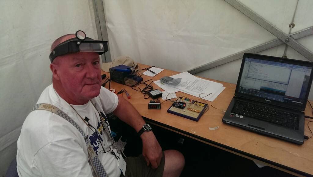
Had a great day at the Dublin maker fare yesterday. Flashed a couple of them for our members. Was hoping for more but they will come.

All the "hackers" I talked with about this think that Mats is a "Mega Master Flasher"

e2ugeguq.jpg
 
Very cool!
Thanks a lot for the support, Will_D! And thanks for posting back! Is that you in the picture?
I'm glad you had a good time and was able to help a few brewing buddies out!
 
Yes unfortunately!

My back was killing me hence the slouch.

BTW: One of the coolest bits of kit on show (forget the 3d printers and the laser cutters) was a home made DNA sequencer from a bunch of bio hackers in Cork! It was computer controlled and could assemble the amino acid bases to order!
 
I have some good news and some bad news to report:

The Good News: I think I've secured a source for the correct controller version

The Bad News: You have to buy a minimum of 100pcs in order to buy from them

More Bad News (for me anyway): In the process of finding a source, I got stuck with 100pcs of the wrong version

If this turns out to be a reliable source, I'll order an extra 50pcs of the good controllers when I build my next batch of "The Black Box" and will sell them at cost to the DIY crowd. In the meantime, you'll see me selling STC-1000's on Ebay; do NOT buy these, as they are the v1.1's I'm getting rid of.

Looks like I jumped the gun with this post... I just received my 2nd batch of controllers and I am now the proud owner of 200 units of the wrong version! (STC-1000_Power_V1.1)

If/when I do finally secure a reliable source for v1.0's, I'll let you guys know, but looks like this particular source was a dead end. In the meantime, if anyone has developed a particular affinity for v1.1's, I'm your guy! :cross:
 
That REALLY sucks...

I wonder how hard it would be to install a Arduino Pro-Mini inside of one.. I've got a 1.1 laying around, I'll have to crack it open and take a look.

I don't think physically installing the arduino would be much of a hassle (unless you wanted it tidy). The code would be the tricky bit, and while Alpha has got it seemingly down for the PIC I would expect some changes required to have a working code in the arudino (Don't know if the .hex files supplied by Alpha are written in assembly or something higher, but most likely not directly transferable into the language that arduino uses)
But (and without taking a V1.1 apart or really knowing what I am talking about) what the STC1000 does give you is a nice package with a 2+1 8 segment display, some LEDs, 4x buttons, 120/240VAC - 12VDC power supply, 2x 10A power relays (maybe 15A), 1x Sensor input with voltage divider (potentially two with a couple more parts).
My biggest question would be how is the display controlled?
 
Also Alpha how is the PID version going? I have tried searching the thread but since PID is only three letters it doesn't return anything!
It would be an awesome combination of your 2 projects on here to have the DIY cheap RIMS tube run BY a STC1000PID!
 
My biggest question would be how is the display controlled?

It's multiplexed if I remember correctly.

Code:
 * Schematic of the connections to the MCU.
*
* PIC16F1828
* ------------
* VDD | 1 20 | VSS
* Relay Heat RA5 | 2 19 | RA0/ICSPDAT (Programming header), Piezo buzzer
* Relay Cool RA4 | 3 18 | RA1/ICSPCLK (Programming header)
* (Programming header) nMCLR/VPP/RA3 | 4 17 | RA2/AN2 Thermistor
* LED 5 RC5 | 5 16 | RC0 LED 0
* LED 4, BTN 4 RC4 | 6 15 | RC1 LED 1
* LED 3, BTN 3 RC3 | 7 14 | RC2 LED 2
* LED 6, BTN 2 RC6 | 8 13 | RB4 LED Common Anode 10's digit
* LED 7, BTN 1 RC7 | 9 12 | RB5 LED Common Anode 1's digit
* LED Common Anode extras RB7 | 10 11 | RB6 LED Common Anode 0.1's digit
* ------------
*
*
* Schematic of the bit numbers for the display LED's. Useful if custom characters are needed.
*
* * 7 -------- * -------- * C
* / 7 / 1 / 7 / 5 2
* 2 / / 6 2 / / 6 ----
* ------- ------- 2 / 7 / 6
* * / 1 / / 1 / ---
* 3 5 / / 3 5 / / 3 5 / 1 / 3
* -------- * -------- * ---- *
* 4 0 4 0 4 0
*

Well that makes things a bit clearer :D So as before "all" you need to do is some coding... oh and some insanely good soldering skills :D
 
Ah, Sh!t :tank:

I hoped, and for a moment thought you'd discovered the whole grail of STC supply there.

Perhaps return them as having the wrong specs? <ugh>

Well... I'm forever the optimist! I ordered 250 units from a new potential supplier in China :drunk: 3rd time's the charm, right!??

I did at least get them to send me a picture of the board and confirm that it had the correct hardware this time, but we'll see! I'll make at least 50 of these available to the DIY crew, should they prove to be the right version (fingers crossed, don't think I can afford to roll the dice another time!)

I'm keeping my fingers crossed for you. Although it makes typing, and brewing, harder, it's for a noble cause. You're the man! :rockin:
 
Well... I'm forever the optimist! I ordered 250 units from a new potential supplier in China :drunk: 3rd time's the charm, right!??

I did at least get them to send me a picture of the board and confirm that it had the correct hardware this time, but we'll see! I'll make at least 50 of these available to the DIY crew, should they prove to be the right version (fingers crossed, don't think I can afford to roll the dice another time!)

I am certainly interested if you are able to get the right ones. Fingers Crossed!
 
Hi guys!

If anyone is interested I just pushed to a new project on github. It's the STC-1000+ mash control firmware.
Tonight I've been trying to patch up the missing bits and get something presentable. It is still very much alpha code stage, but with your help it might amount to something usable.
No manual yet, but if you've used STC-1000+ before, you should be ok.

So what is it? Well, it is pretty much STC-1000+, but with 1 minute steps (instead of 1 hour steps), ramping is dropped (it is not of much use here either...) and it uses PI control (instead of thermostat). PI as in proportional and integral (the D part, derivative, is left out as it is more trouble than good for this application).
The PI control is implemented in 16-bit integer arithmetic, which was no small task, but I think I got it working reasonably well.

What's new? Under the set menu, you will find some new options:
Pd: period (1,2,4,8,16,32 or 64 seconds)
cP: Proportional gain
cI: Integral gain
OP: Set output
OL: Min PI output
Oh: Max PI output

I'd suggest using period time 1 or 2, if you want to try it out still using the internal relay (instead of driving an SSR), you might want to try maybe 16 or 32 to spare the relay.
Start with low cP and cI (maybe 16 and 1).
OL and Oh should limit the minimum/maximum duty the PI will produce.
Then there are new run modes, profiles as usual, but also ct (constant temperature) and cO (constant output). In cO mode the value in OP, will be output, in ct mode the PI will aim for the setpoint.

Only heating is implemented, the cooling relay is not used (at least for now).

Also, I've been fiddling with a webpage, to attempt to simulate how the PI algorithm could behave (it is located under the simulate folder). It is only in SI units, but you can try it out if you want.

I guess I've forgotten a bunch of stuff that you'd want to know, if you want to try it out, but ask and I'll try to answer.

The files are located here: STC-1000+ Mash control (work)

Please, do help me to try and find bugs, I guess there will be a few (remember still alpha stage).

Cheers!
//mats
 
STC-1000+ mash control firmware.

Mats - this has honestly made my night. I noticed you mentioning this project in passing a few times, but I've just put in the order for camlocks and a pump to build up a RIMS system - the last bit was a control system.

Thank you again for putting together this amazing improvement - if you're ever in Montreal, please come out for a pint on me.
 

Latest posts

Back
Top