Stc-1000+

Homebrew Talk - Beer, Wine, Mead, & Cider Brewing Discussion Forum

Help Support Homebrew Talk - Beer, Wine, Mead, & Cider Brewing Discussion Forum:

This site may earn a commission from merchant affiliate links, including eBay, Amazon, and others.
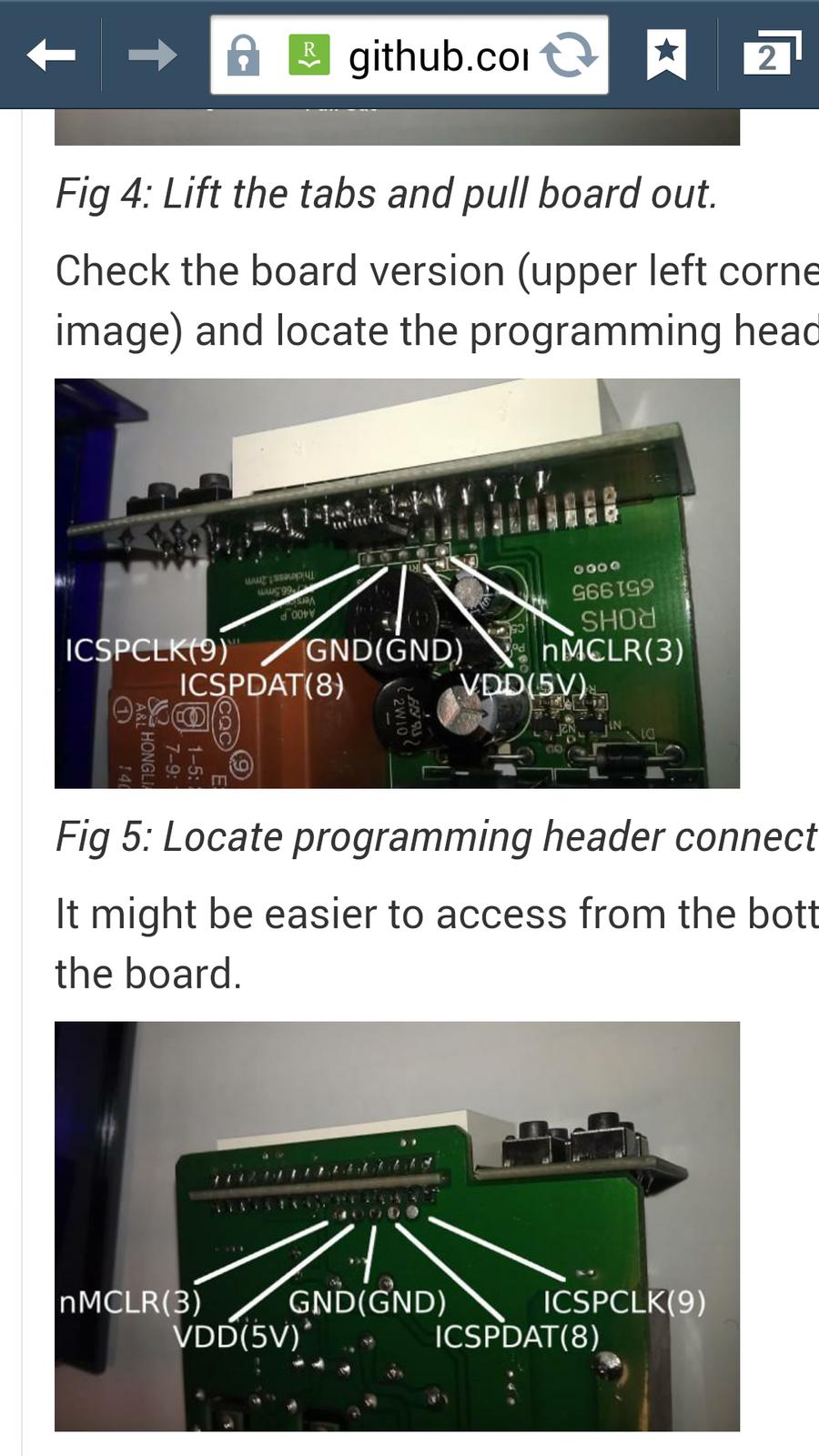
Is the firmware upgrade still for version 1.0 only ?I have a stc 1000 with
"A400 p ver 1.0" on the inside main board . BUT it says a400_D&M version 1.1 on the display board above the input buttons .
Can this stc1000 be flashed ?
Thanks
Stacy
 
Pic

Screenshot_2014-10-07-19-04-07.jpg
 
Is the firmware upgrade still for version 1.0 only ?I have a stc 1000 with
"A400 p ver 1.0" on the inside main board . BUT it says a400_D&M version 1.1 on the display board above the input buttons .
Can this stc1000 be flashed ?
Thanks
Stacy

Yes, this is a flashable unit.
 
Dear doctorjames, are you sure you have put enough thought into this?
I mean after all we are talking about fermentation of homebrewed beer here, if you haven't actually sat down and made a thermodynamic model of your fermentation vessel that accounts for the fluid motion due to yeast activity at different stages, stratification and convectional currents, then what is the point? :)
Seriously, I don't judge if you have, brewing is awesome, there is something in there for everyone. Some want to weld and/or solder, some culture yeast, some experiment with recipe formulation, build gadgets or whatever. There is more than enough fields of expertise you could sink your teeth into if you are interested. To me there is no need to justify going overboard on anything, it is a hobby and you do what you want with it.
I think in this case though (as probably in many others) you reach a point of diminishing returns pretty quickly. If brewing better beer is the goal, then some temperature control (ice bottles, wet cloth etc) is a lot better than none, and a decent one (thermostat), while probably even better, won't make as much difference. I agree that there are many variables and that most probably don't have the level of control they think they have. Somehow, in the end, most of the time, you end up with a decent pint anyway :)

Oh yeah, and in other news (and totally off topic btw). Yesterday I became a father to a beautiful little baby girl :) Yay!
 
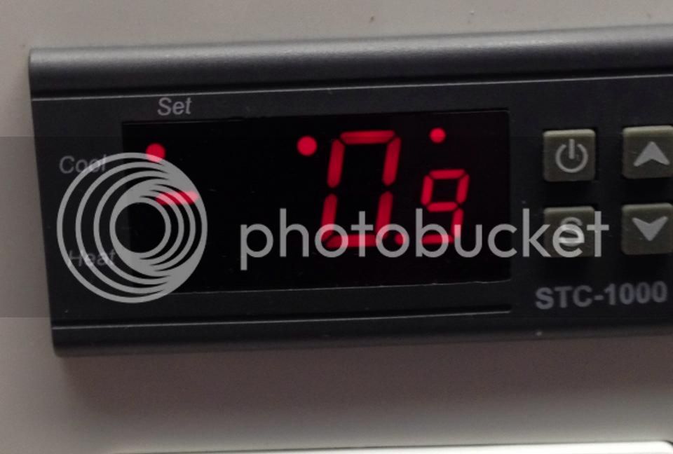
ver 1.06 I can't get out of this screen.unplugged the power several times and this is the default display.I can move thru all of the menus w/o a problem.Thanks


stc1000ver106.jpg
 
Do a quick press of the power button to cycle, that is s the temp probe #2 display, which is not connected.

Oh and congrats alphaomega!
 
That would just be the degree symbol when a temperature is shown. In the celsius version a 'C' is also shown, which makes it a bit more explanatory. No 'F' available on the display though.

And thank you all for the congrats! It warms our already overjoyed hearts :)
 
That would just be the degree symbol when a temperature is shown. In the celsius version a 'C' is also shown, which makes it a bit more explanatory. No 'F' available on the display though.

And thank you all for the congrats! It warms our already overjoyed hearts :)

Just curious, is there a schematic that shows every LED on the display with a legend as to what they mean and when they'll be shown?
 
Congratulations ΑΩ!! Life has just changed forever - in a good way!!

(except, dev time for the STC1000+ just got smaller :D)
 
All the parts need for adding a second temp probe on the slow boat from China. Does anybody have any advice on adding the second probe? I've read through this thread and also the readme, so I understand what needs to be done, but am wondering if anyone has any pictures of what they did.

Cheers!

I'm interested in the same advice.

If I use the programmer header for my resistor and second probe connections, will I be able to reprogram with these connections in place? Or, do they need to be disconnected first. I'd like to be able to reprogram updates without taking the thing apart.

(Sorry if this was covered already.)

I don't have any pics, I've been adding the SMD resistor and replaced the screw terminal with a three pole equivalent.
Now, you can program the unit with the connections in place, no problem. If you already have a connector to plug in your programmer, I would simply make another matching connector that houses the resistor and second probe instead, and swich between them when programming. That would be the easiest solution.

Cheers!
 
Just curious, is there a schematic that shows every LED on the display with a legend as to what they mean and when they'll be shown?

No, not really. In the header file, there is the pinout, and in the manual there are bits of info strewn about. I've been planning on adding a section for a quick explanation of the LEDs and buttons. But, you know... Life and work... Besides, I mostly end up hacking code instead, because it is something I enjoy more than documenting. But I really want the documentation up to scratch as well, as it is what most will be referring to (not that many read the actual code :) ).
If anybody want to help out, I'd be all for it. Will and Disney7 have been very good at proof reading, editing and beeing all around helful in getting the documentation to the state it is now.

Cheers!

I've been searching for an image of a display schematic that shows ALL LEDs on the display (similar to the display in this picture) but haven't found one. I plan on making my own this weekend that could hopefully be used as a quick reference. There are so many dots and blinking dots that I was just hoping we could easily define with a picture. This came up because I was completely unaware that the dot in the upper right hand corner was supposed to be a degrees symbol! I like it now that I know! :D

I'll post the image once it's created in case any of you want to use it.
 
I'm finally at a point where I can datalog and do some testing on the dual probe setup. Just have to find time to add the second probe. Hopefully I'll have some data in a week or two and should have some decent default settings.
 
I've been searching for an image of a display schematic that shows ALL LEDs on the display (similar to the display in this picture) but haven't found one. I plan on making my own this weekend that could hopefully be used as a quick reference. There are so many dots and blinking dots that I was just hoping we could easily define with a picture. This came up because I was completely unaware that the dot in the upper right hand corner was supposed to be a degrees symbol! I like it now that I know! :D

I'll post the image once it's created in case any of you want to use it.

You can use what I have come up with this far, if you like.
I had to rename it to xml to attach it, but it is an svg file.

Cheers!

View attachment stc-1000_front.svg.xml
 
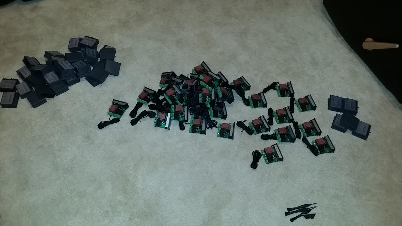
anyone actually kill a adruino uno? I flashed about 25 controllers tonight, and now the arduino won't come up as a com port, makes no difference to computer when I unplug and plug it back in, on multiple computers. USB cable seems to be okay checking continuity. Not sure what happened, but my flashing fun comes to an end about 25 controllers short :(

2 LEDs are lit up on the board, the ON green one, and a orange one with a L close to it.

Greg
 
What is the wattage of the resistor for the second probe? Is it 1/4W?

Also Congrats Alpha!

Cheers!

Not important.
Worst case, the resistor drops the entire 5v. That would mean 0.0025 watts by my calculations. Just get the best precision resistor you can.

Cheers!
 
I'm finally at a point where I can datalog and do some testing on the dual probe setup. Just have to find time to add the second probe. Hopefully I'll have some data in a week or two and should have some decent default settings.

I meant to reply to this. This is awesome news to me David. I wanted to do some experimenting with this myself, but have not had the time. I am eagerly awaiting your results!

Cheers!
//mats
 
They are all v1.0 luckily. Picked them up from the city digital or city image I forget what they are called but many in this post have bought from them on amazon.
 
My new arduino came in today, was able to flash the remaining 30 controllers, still not sure what happened to the first one, kinda weird
 
Alpha, do you know when 1.07 is out? No stress, but have a few ready for flashing. 1.06 works perfect btw :)
 
Well, don't hold your breath...
I've started development and there is really not all that much that is going into it, but right now I don't have any time (for anything basically...).
I really can't say, even when I get it done, I like to have it 'stabilizing' in the work branch for a while before I make an 'official' release.
 
Thank you for reply. Just wondering if it was around the corner. Take care of family "development" :) best luck.
 
Alpha, wanted to say thanks again. I've been using the STC+ but only in limited way and finally ventured into profiles. The logging shows just how beautifully this thing operates (I also like it showing the frequency shift days 2-4 during exothermic fermentation). This has been just wonderful.

brown porter graph.jpg
 
Back
Top