• Please visit and share your knowledge at our sister communities:
  • If you have not, please join our official Homebrewing Facebook Group!

    Homebrewing Facebook Group

Spa Panel Wiring

Homebrew Talk

Help Support Homebrew Talk:

This site may earn a commission from merchant affiliate links, including eBay, Amazon, and others.

RMessenger

Well-Known Member
Joined
Oct 15, 2014
Messages
48
Reaction score
1
Location
Rochester
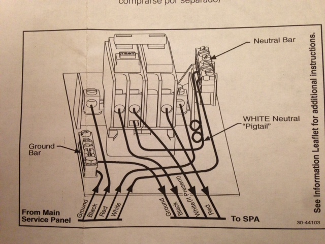
How can I wire this 50 amp spa panel with 12/2 wire (please note that I'm only using it for the GFCI protection and will clearly mark it as a 20 amp line)?
IMG_2007.JPG
 
So you'll have 2 hot wires and a ground? I think the way that works is you'll wrap red (or black) tape around the ends of the white wire and use it like the red wire in the diagram. You won't have a white wire.

The trick is where does the white "pigtail" sense wire go... I bet it goes to the ground bar. (either that, or it goes by itself on the neutral bar -- basically disconnected) Does the manufacturer have any instructions for wiring a pure 240V circuit? What's on that additional leaflet?
 
I was thinking that I would just wire the white wire as a red, too. However, I think the white pigtail is a problem. Is my only option to get a new GFCI breaker that doesn't require the red wire? I'm running it off of an existing outlet, so using different wire isn't much of an option.
 
The one you have should work, I just don't know enough about 2-pole GFCI's to know where the pigtail goes when there's no neutral wire.

If you need to power a small 120v load as well as a big 240v load, I would wire it like that figure in post 8 of the other thread but without the jumper between the ground and neutral bars. (the equipment ground will float; not ideal, but the GFCI will provide protection)

ETA: according to this http://forums.mikeholt.com/showthread.php?t=54058 the pigtail is just for the test button. Leave it disconnected, or by itself on the unused neutral bar, or to the ground bar if you want the test button to work.
 
I'm pretty sure that diagram is wrong. The only place you can connect ground to neutral is in a service entrance panel (usually the main breaker box.) The spa disconnect box is not a service panel.
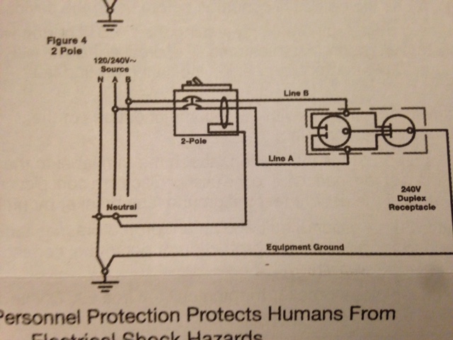
You are correct that it is not code compliant. However, it does work, and is best used as a pluggable device so as not to violate code in permanent house wiring. There are many pros and cons discussions on this forum.
 
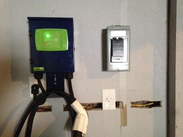
I wired the black to black, white to red, ground to the ground bar, and left the neutral pigtail connected to the unused neutral bar. It trips the breaker. I'm piggybacking off of an existing outlet that I use for an EV charge station (pigtailed wires). The charge station works fine, but the spa panel is freaking out.
 
It was my understanding at the time that I purchased the spa panel that that was less expensive than a 240v GFCI cord.
 
I'm pretty sure that diagram is wrong. The only place you can connect ground to neutral is in a service entrance panel (usually the main breaker box.) The spa disconnect box is not a service panel.

Negative Ghostrider, if you look at the first one, the green wire coming out of the box is acting as the gfci "neutral" not a ground. In the second image the green passes through the grounding bus and continues on. In no way, shape, or form is the green from the main service panel connected to a neutral bus.
 
[QUOTEIn no way, shape, or form is the green from the main service panel connected to a neutral bus.[/QUOTE]


It is in the main panel and a few other scenarios if a grounding wire is not ran to sub panel for old/poor work.

Sent from my iPad using Home Brew
 
I've finally had a chance to upload a picture of the instructions for 2 pole that came with the spa panel. They're not as clear as the instructions that I posted at the start of this thread, so I'm a little confused, but doesn't it look as if the instructions say to wire 2 pole the way Watermelon83's link says to?

IMG_2008.JPG
 
I've finally had a chance to upload a picture of the instructions for 2 pole that came with the spa panel. They're not as clear as the instructions that I posted at the start of this thread, so I'm a little confused, but doesn't it look as if the instructions say to wire 2 pole the way Watermelon83's link says to?

Are you going to wire your spa panel direcly to distribution panel or going to plug it to 3 prong outlet?
 
[QUOTEIn no way, shape, or form is the green from the main service panel connected to a neutral bus.
It is in the main panel and a few other scenarios if a grounding wire is not ran to sub panel for old/poor work.

Sent from my iPad using Home Brew[/QUOTE]


Your quote and response is completely out of context.
 
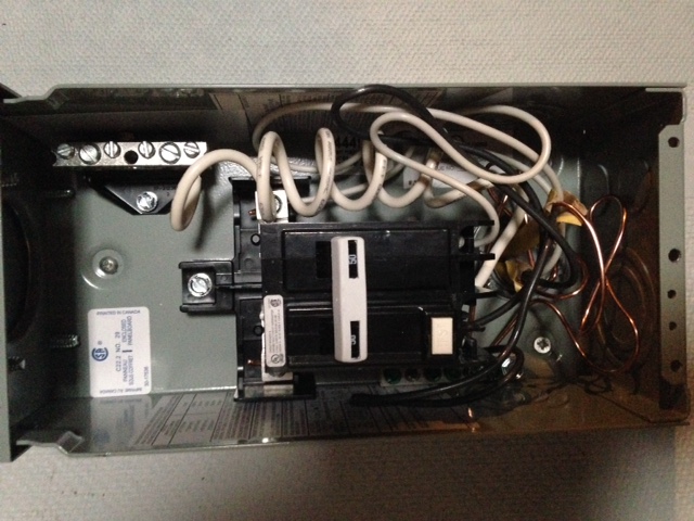
Here are a couple pictures. I haven't had the time to change the wiring (it's still black to black, white to red, ground to ground, with the neutral pigtail attached to the neutral bar but nothing else connected to the neutral on the breaker or the neutral bar). I'm planning on wiring it according to the diagram provided in the link on the first page of this thread, but I am a little worried about the conversation of that not being right. Also, I left a lot of extra wire in the spa panel (I would rather have too much than too little), so it's hard to see where things go. I could clean that up when I get everything set and add red tape to mark the white wires as red.

IMG_2016.JPG


IMG_2017.JPG
 
P-j's diagram is right and safe, if that is what you are referring too. Since you don't have a four wire feed, the grounding in panel discussion is irrelevant to your application.
 
P-j's diagram is right and safe, if that is what you are referring too. Since you don't have a four wire feed, the grounding in panel discussion is irrelevant to your application.


I just went back to PJ's post that you linked. Both of those show 4 wire going out of the panel. So how does the wiring change if I'm only running 3 wires out?
 
My original question in that thread was for a four wire system. The ground isn't needed. P-J posted those to show me how best to incorporate it. If your running three wire out just use the bottom diagram and ignore the diagrams green wire.
 
Just to be clear. You should have two hot wires and the neutral for a 240v element. If your incoming connection color options are red black and white then red and black are your loads white is your neutral.

Going to the panel you NEED those three, not the ground. If I follow you correctly, you want that green wire connected to white not green.
 
Here is an example of what yours should look like. Notice the green wire and white pigtail are bonded. This is because the gentleman used the green wire to carry his neutral rather then ground, which I believe is exactly what your trying to do.

https://www.homebrewtalk.com/f170/spa-panel-wiring-dummies-266751/index2.html#post3392248

Going out to the kettle the white wire becomes your bonding ground, attach it to the box or kettle, only the black and red get connected to the element.
 
Just to be clear. You should have two hot wires and the neutral for a 240v element. If your incoming connection color options are red black and white then red and black are your loads white is your neutral.

Going to the panel you NEED those three, not the ground. If I follow you correctly, you want that green wire connected to white not green.

My incoming wires are black and white with a ground (12/2 romex wire that is used for the EV charge station). It was my understanding that with a pure 240v device you don't need a neutral, so the white wire is used as a red wire (marking it with tape) providing the two hot wires but no neutral. Is this wrong?
 
Yes it wrong. You need the neutral to your gfci for the bare minimum of safety. You need it going to the kettle to use gfci protection.
 
Back
Top