Spa Panel GFCI - 3 wire source to 3 wire appliance...is it doable?

Homebrew Talk - Beer, Wine, Mead, & Cider Brewing Discussion Forum

Help Support Homebrew Talk - Beer, Wine, Mead, & Cider Brewing Discussion Forum:

This site may earn a commission from merchant affiliate links, including eBay, Amazon, and others.

snowveil

Well-Known Member
Joined
Feb 23, 2010
Messages
713
Reaction score
90
Location
Lebanon
I apologize that this question has probably been asked a billion times, but any threads I find seem to turn into huge debates and I get lost in the weeds trying to decipher what's relevant to me and what's not.

Here's my less-than-ideal situation. I live in a 2nd story apartment in which I do NOT have access to any breaker panels. I live in an old building in which the main breaker panel is in the basement, which is not available to me because it is rented out to a business on the first floor. If a wire gets tripped during business hours, I can ask the business to allow me to access to breaker panel to reset the breaker, but if something trips on the weekend I'm pretty much SOL.

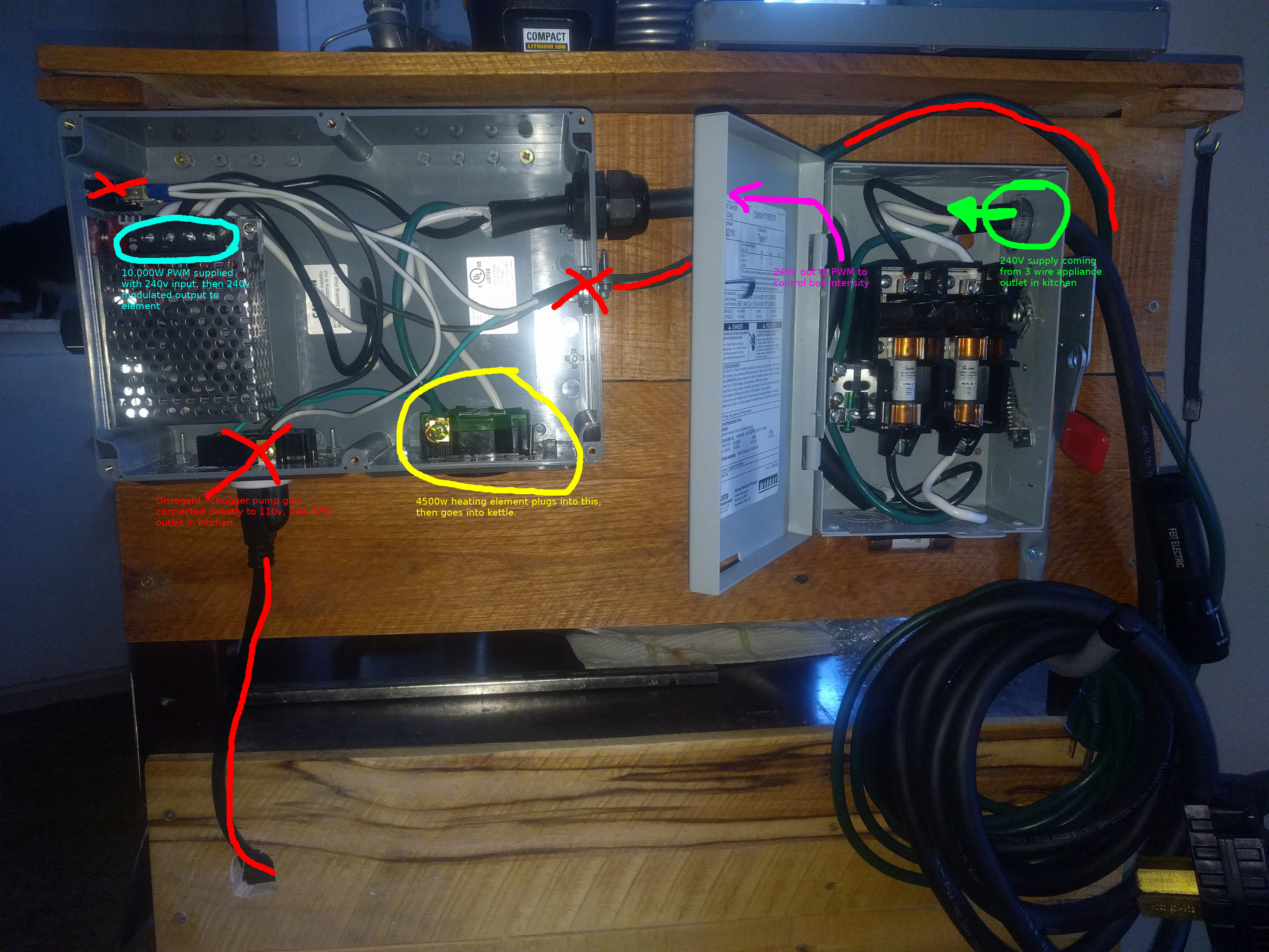
My kitchen stove is powered by a 3-prong outlet with a 40A breaker in the basement. My rig is pretty simple...it involves a 2-pole safety switch with 30A fuses coming from the outlet, then going into a 240v 10,000w PWM that simply "dims" the power going to my 4500w element.

I do not need 110v coming out of the spa panel. I have a 110v Chugger pump in my system, but I plug it directly into a 20A GFCI outlet in my kitchen.

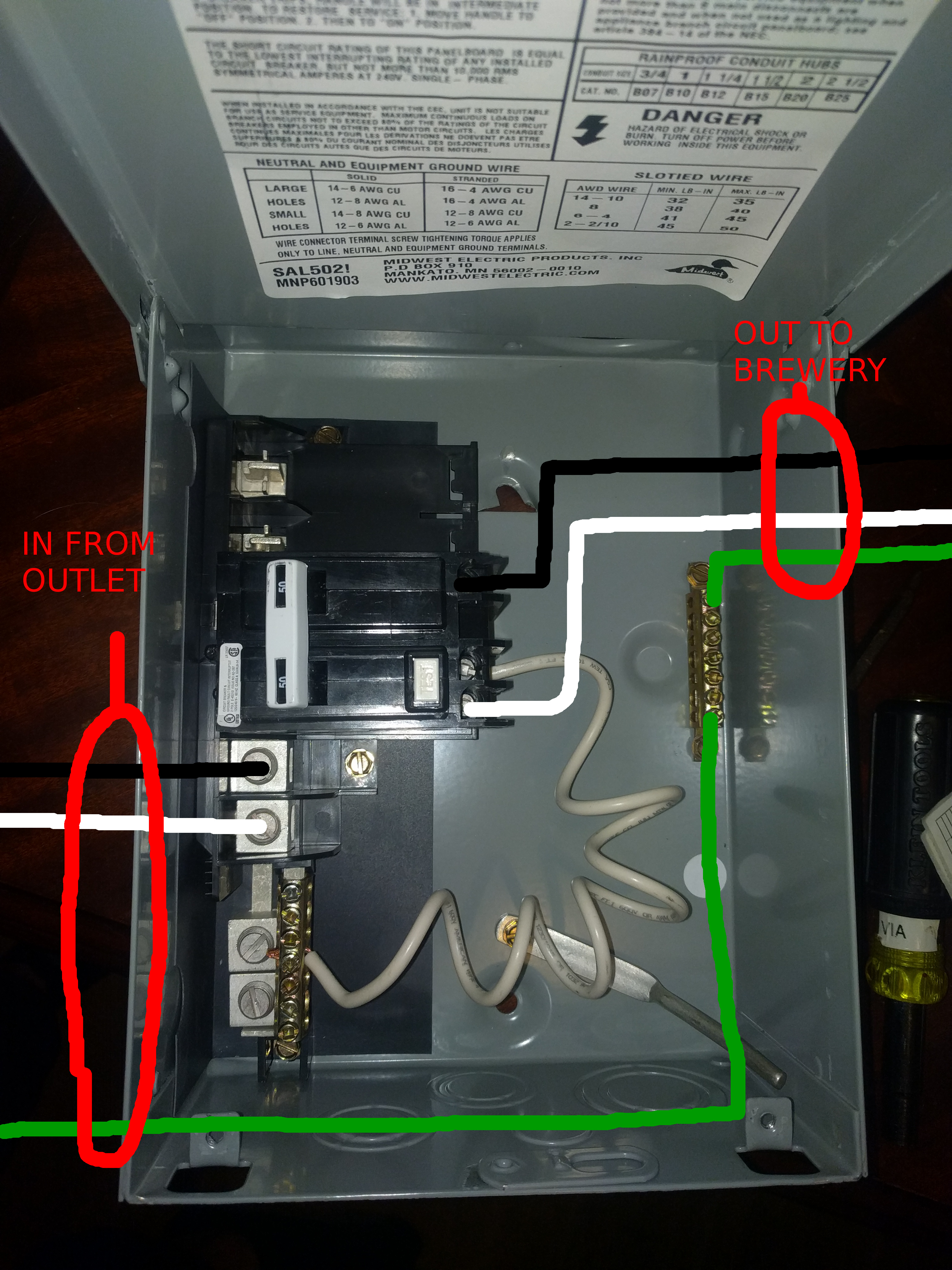
As it stands, I simply want to put a spa panel in between the 3 wire appliance outlet and the fused safety switch. I intend to mount the spa panel to my rig...not permanently on the wall. I already have the Midwest 50A GFCI Spa Panel that often is recommended around the forum. ( https://www.homedepot.com/p/Midwest...el-Disconnect-with-GFI-UG412RMW250P/100686230 )


As for the spa panel...I've seen 3-wire input to 4-wire output diagrams, 4-wire input to 4-wire output diagrams, and even 4-wire input to 3-wire output diagrams...but I haven't come across a 3-wire to 3-wire solution. Is this doable, and if so, can someone please help me with a diagram?


Here's my current setup for reference. The system works, but is not currently GFI protected. I want to install the spa panel BEFORE the neon green annotated section:
annotated_brewery_wiring.jpg


Any help would be greatly appreciated...thank you!
 
I'm not 100% sure as it was a few years ago I built my system but I think you have to have a 4 wire setup for the general spa panel to work
 
Will work fine. Just connect the two hots to the appropriate breaker inputs and connect the incoming ground to the ground bus in the spa panel. Connect the load hot wires to the breaker outputs, wire the load ground to the spa panel ground bus, and wire the white pigtail from the breaker to the spa panel neutral bus (just to keep it from shorting to anything else.) There will be no other connections to the spa panel neutral bus.

Brew on :mug:

So just for clarification, does this look good?

Thanks so much!

spa_panel_annotated.jpg
 
Looks good from what I can tell. However, I'm not certain if the "Test" button on the GFCI breaker will function correctly without a neutral coming into the spa panel, but the GFCI will protect your brew control box. It would be possible to wire up a simple GFCI test button in your brew panel if the official test button doesn't work.

Brew on :mug:


He talks about 3 wires at 4:33. Hope that video helps you.
 
Looks good from what I can tell. However, I'm not certain if the "Test" button on the GFCI breaker will function correctly without a neutral coming into the spa panel, but the GFCI will protect your brew control box. It would be possible to wire up a simple GFCI test button in your brew panel if the official test button doesn't work.

Brew on :mug:

thoughts on the gfci operating properly if fault is downstream of the power supply? can't say i have any experience with this but seems like maybe there won't be a current imbalnce on the line side of a switched power supply?
 
thoughts on the gfci operating properly if fault is downstream of the power supply? can't say i have any experience with this but seems like maybe there won't be a current imbalnce on the line side of a switched power supply?
Without a neutral, the sense coil in the GFCI will only be sensing the differential current on the two hot lines. A fault downstream of the GFCI will cause the differential current to be non-zero, so the GFCI will trip.

Brew on :mug:
 
Why would a switching power supply cause a current imbalance. The designs I am familiar with all just run the incoming AC thru a diode bridge to create a DC voltage which is then pulse width modulated and sent thru a low pass filter. Sometimes there is a step-up transformer in front of the low pass filter if the output voltage needs to be higher than the input voltage. I don't think a diode bridge causes a current imbalance between the source and sink input lines.

Brew on :mug:

i honestly don't know, hence the question. it isn't imbalance like a fault but rather noise (common mode or other) that the gfci sees as a fault. similar problem with a vfd and some electric welders on gfci circuits.

i would think a switched power supply 'breaks' the circuit in the same way a transformer does (a gfci on the primary side of a transformer will not provide gfci protection on the secondary) so even if the gfci didn't trip during regular operation, it may not do anything on a load-side fault either.

sounds like the op already has this stuff so worst case, plug it in and see what happens. should definitely rig up a test switch on the power supply output to see if it trips the upstream gfci. that's my advice anyway...
 
i honestly don't know, hence the question. it isn't imbalance like a fault but rather noise (common mode or other) that the gfci sees as a fault. similar problem with a vfd and some electric welders on gfci circuits.
I did some reading, and indeed some switching power supplies do have internal leakage issues which can trip GFCI's under some conditions. I think the power supplies can be designed to avoid this, but low cost supplies may not go to the extra expense.

i would think a switched power supply 'breaks' the circuit in the same way a transformer does (a gfci on the primary side of a transformer will not provide gfci protection on the secondary) so even if the gfci didn't trip during regular operation, it may not do anything on a load-side fault either.
I think you are correct, but it probably depends on how the power supply is designed. In the OP's case, I think the supply may just be an SCR that chops the incoming AC waveforms to provide a lower RMS voltage. If that is the case, then I would think that GFCI protection flows thru the power supply and will trip on leakage at the load.

sounds like the op already has this stuff so worst case, plug it in and see what happens. should definitely rig up a test switch on the power supply output to see if it trips the upstream gfci. that's my advice anyway...
I agree, OP really needs to put a test circuit on the output side of the power supply to make sure that a leak to ground will in fact trip the GFCI.

To the OP: The test circuit is just a switch in series with a 1W, 10K ohm resister connected between one of the power supply outputs and ground.

Brew on :mug:
 
looking closer at the photo, the 'power supply' appears to be one of those scr voltage regulators that are an affordable alternative to ssr/pid control. lots of those in use and not a rash of gfcis tripping. i would think the gfci would pick up on a load-side fault based on this circuitry but seems the only good way is to give it a test.
 
looking closer at the photo, the 'power supply' appears to be one of those scr voltage regulators that are an affordable alternative to ssr/pid control. lots of those in use and not a rash of gfcis tripping. i would think the gfci would pick up on a load-side fault based on this circuitry but seems the only good way is to give it a test.
Agreed.

Brew on :mug:
 
Simply for archival purposes...

I wired the Spa panel up as described in this thread and went through a brew day with zero issues. The test button on the spa panel GFCI functions as it should, as well.

Thanks to everyone for the help!
 
Simply for archival purposes...

I wired the Spa panel up as described in this thread and went through a brew day with zero issues. The test button on the spa panel GFCI functions as it should, as well.

Thanks to everyone for the help!
Thank you for coming back and reporting in this thread. I am doing exactly the same wiring yet my test button on breaker does not work. I was surprised when you said yours works. Mine will work if I wire the pigtail to the ground buss instead of neutral.
Do you have any other wires on the neutral buss in your spa panel?
 
In a 3 wire system your white and black wire are both now hot. Paint or tape the white wire black. Your ground remains a ground. One per wire per fuse and to the ground terminal, repeat in the control panel


Here's my current setup for reference. The system works, but is not currently GFI protected. I want to install the spa panel BEFORE the neon green annotated section:
annotated_brewery_wiring.jpg


Any help would be greatly appreciated...thank you![/QUOTE]
 
Bill, I am not sure if you were answering my post or not, but I am only talking about the spa panel area, in fact I am not using the fuses panel shown ... thanks

In a 3 wire system your white and black wire are both now hot. Paint or tape the white wire black. Your ground remains a ground. One per wire per fuse and to the ground terminal, repeat in the control panel


Here's my current setup for reference. The system works, but is not currently GFI protected. I want to install the spa panel BEFORE the neon green annotated section:
annotated_brewery_wiring.jpg


Any help would be greatly appreciated...thank you!
[/QUOTE]
 
Agreed.

Brew on :mug:
Doug, would you comment on this? Essentially, my test button on my spa panel will not work when pigtail is on neutral bar ( by itself, not connected to anything), BUT if I put the pigtail on the ground bar , the test button works? Should I do that?

Additional Info: a 10K resistor between one hot and ground trips it, so does that mean it is working even though test button does not?
 
Last edited:
Doug, would you comment on this? Essentially, my test button on my spa panel will not work when pigtail is on neutral bar ( by itself, not connected to anything), BUT if I put the pigtail on the ground bar , the test button works? Should I do that?

Additional Info: a 10K resistor between one hot and ground trips it, so does that mean it is working even though test button does not?
Yes, put the pigtail on the ground bar. The purpose of the pigtail is to leak a small amount of current to neutral or ground from a point past the current sensing transformer in the GFCI. The current sensing transformer measures the vector sum (magnitude and phase) of the three currents on hot1, hot2, and neutral. In normal operation the sum of currents will be zero. If there is a current leak downstream of the GFCI, then the sum of currents is not zero, and the GFCI trips. The pigtail creates an unbalanced current when the test button is pressed, and the GFCI will trip if it is working correctly. For the pigtail to do its job, it has to be connected to a conductor that will accept the current flowing in the pigtail. If the pigtail is disconnected, then no current can flow thru the pigtail, and the test button will not work.

Brew on :mug:
 
thank you for the info. I thought that would be the case, yet https://www.homebrewtalk.com/forum/...e-appliance-is-it-doable.652555/#post-8389458 claims the test button works for him and he has nothing connected to the pigtail, so I was confused.


Yes, put the pigtail on the ground bar. The purpose of the pigtail is to leak a small amount of current to neutral or ground from a point past the current sensing transformer in the GFCI. The current sensing transformer measures the vector sum (magnitude and phase) of the three currents on hot1, hot2, and neutral. In normal operation the sum of currents will be zero. If there is a current leak downstream of the GFCI, then the sum of currents is not zero, and the GFCI trips. The pigtail creates an unbalanced current when the test button is pressed, and the GFCI will trip if it is working correctly. For the pigtail to do its job, it has to be connected to a conductor that will accept the current flowing in the pigtail. If the pigtail is disconnected, then no current can flow thru the pigtail, and the test button will not work.

Brew on :mug:
 

Latest posts

Back
Top