• Please visit and share your knowledge at our sister communities:
  • If you have not, please join our official Homebrewing Facebook Group!

    Homebrewing Facebook Group

Single Tier, 3 Pump, BCS-462, Automated Rig

Homebrew Talk

Help Support Homebrew Talk:

This site may earn a commission from merchant affiliate links, including eBay, Amazon, and others.
Hey JonW, just put the finishing touches on my system that borrowed quite a few ideas from yours. At first I didn't want to do 3 pump but I'm beginning to want it now. What did you use for an enclosure for the expansion board?
 
Hey JonW, just put the finishing touches on my system that borrowed quite a few ideas from yours. At first I didn't want to do 3 pump but I'm beginning to want it now. What did you use for an enclosure for the expansion board?

There is no expansion board. Do you mean the BCS or the relay board? The relay board is in a project case. Both are mounted under the stand. My lower shelf is sealed w/ silicone around the tubing, so no drips get to anything under the shelf.
 
Ah yes I meant relay board thank you. Great work. Hoping to get mine fine tuned this evening and get some photos up. Cheers!
 
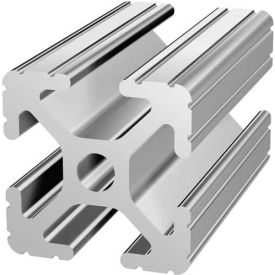
Question for you guys - has anyone tried using aluminum t-slots for a build? Any downsides? Right now I have a TopTier, but am liking this design better

T-slot:
8IN_1010-72.jpg
 
The power supply you get really depends on how much current you need. I used 12V ball valves for the liquid side, but I used 120V valves for the gas solenoids because the 12V ones needed a lot of current. 12V solenoids need something like 800 mA, so for 3 valves, you need 2.4 amps. That's a lot of 12V current. Instead, use the 120V gas valves and trigger them with an SSR just like the pumps. They will only need a couple of milliamps to trigger. The 12V ball valves only use something like 40 mA to operate. A single 1 amp 12V power supply can run all the ball valves and relay board, with plenty of current to spare.

I am purchasing a 12v 1A power supply. Would you look at the attached pdf and see if I am wiring this correctly?

View attachment 8 channel relay module board.pdf
 
Yeah, that looks good.

I wired mine the same, but with a little twist. I actually cut traces on the board and hardwired the input feed for the common pin to 12V + (pos) and then wired the actual common terminal to 12V - (neg). You also have to cut the trace to make this work - I used a dremel to cut it. The reason for this is so I didn't have to use a terminal strip or wire nut and it made the attachment of each valve to the 3 terminals a cleaner setup. I'm not advocating for others to do it this way, I'm just showing how I accomplished it.

Relay-Board-Modified.jpg
 
Awesome build Jon, I just moved back to Socal after living in Az and Tx for far to long. I'd love to come check out a brew day some time in the future. what club are you in and have you heard of the Brewluminati's they are a no club, club so to speak who has monthly meetings at Out of the Park Pizza in Anaheim Hills the last Thursday of each month. we are holding a club 21A Pumpkin SHowdown competition and all entries to be turned in by November 21st. If you have a some pumpkin beer on hand bottle it up and enter the contest.

-=Jason=-
 
Thanks Flomaster. Yes, I've heard of Brewluminati. I'm in Brewcommune. Some of the luminati guys used to be in our club. We're meeting at OPP this month on the 19th. Our meetings are open for any brewers to attend - you don't have to be a member. Come by and check it out.
 
Awesome build! I'm modeling some of my build on your detailing - one question - are the glowfly wired series or parallel?
 
Awesome build! I'm modeling some of my build on your detailing - one question - are the glowfly wired series or parallel?

Parallel. Technically, you could use a separate output for each one and only have them fire with their respective burner, but I just wired them together so that when any burner fires, they all ignite.
 
I started having some intermittent problems with my spark igniters. I swapped them out for the hot surface igniters (HSI's) and they are working great. They are powered by 120V, so I wired all three of them to a single SSR. The BCS powers them up 5 seconds before opening the gas valve and continues to keep them on for another 5 seconds after the valve is opened. They are working flawlessly. I'm now going to suggest these to anyone doing an igniter system like mine.

You can search ebay for "Honeywell Hot Surface Igniter". Model number is Q3200U1004.

This is the one I used:
imgCache-HoneywellGlowflysm_514_0.jpg

Jon, any idea how much amperage the glow plugs pull? I looked on Honeywell's site and couldn't find that information.
 
Jon, any idea how much amperage the glow plugs pull? I looked on Honeywell's site and couldn't find that information.

Each one was about 1 amp. At that level, I decided to just wire them all together on one SSR and have them fire at the same time regardless of which burner valve was opening.
 
I am sure you get asked this a billion times... I hope you will or can give me just a minute of your time. I am building a brew stand very similar to yours and bsomogyi (Coloradoan).. What interests me most about yours is your similarity to mine in that I want to control fermenters and serving units as well from my BCS. I plan to separate the brew stand from the BCS and thus I need a way to connect the Stand to the BCS. I know you use CAT5 for your connections.. I was wondering if you could explain that set up to me? How many connections and to what are they connected.. I plant to have 6 valves (liquid) and 2 valves (gas) for HERMS set up.. Your brewstand (as I remember it) has the pumps plugged into 110 outlets on bottom of stand.. Do you have relays also on the stand that provide power to outlets? I assume the cat 5 provides power to valves when switched on by BCS? Any info is greatly appreciated..
 
I am sure you get asked this a billion times... I hope you will or can give me just a minute of your time. I am building a brew stand very similar to yours and bsomogyi (Coloradoan).. What interests me most about yours is your similarity to mine in that I want to control fermenters and serving units as well from my BCS. I plan to separate the brew stand from the BCS and thus I need a way to connect the Stand to the BCS. I know you use CAT5 for your connections.. I was wondering if you could explain that set up to me? How many connections and to what are they connected.. I plant to have 6 valves (liquid) and 2 valves (gas) for HERMS set up.. Your brewstand (as I remember it) has the pumps plugged into 110 outlets on bottom of stand.. Do you have relays also on the stand that provide power to outlets? I assume the cat 5 provides power to valves when switched on by BCS? Any info is greatly appreciated..

My current configuration is a bit different as I now have a BCS-460 mounted on the wall for the kegerator, fermenter and smoker and my BCS-462 is permanently mounted under the bottom shelf of my rig. However, I will explain the setup as I previously had it with the 462 mounted in the wall cabinet and controlling the kegerator, fermenter and brew rig.

On my rig, I have 7 SSR's that control (3) 110V pumps, (3) 110V gas valves and 1 SSR for the burner igniters. There is also an 8 channel relay board that controls the 6 liquid ball valves and the audible buzzer/alarm. There are also 4 temp probes on the rig.

I have the BCS wired to 3 Cat-5 data jacks. One jack for the SSR's, one for the low voltage relays and 1 for the temp probes. Basically, I wired from the BCS to 3 jacks on the wall and wired the stand from the relays/probes to 3 jacks on the stand. I then use Cat5 cables to connect the two.

There is no "power" going across the cat-5 wiring - it is the low level outputs from the BCS only. I have a single 110V cord on the stand to plug it in and it provides power to the SSR's and a 12V supply mounted under the rig.
 
Do you have a part list for the build interested in a build with motorized valves, just finished a glycol chiller for my fermenter looking to build a nice brewery in the garage and love your setup...
 
I will be heavily copying this design, but will be building a strut version of the stand. Thanks for all the great ideas.
 
Hello JonW,

I just had a quick question about your rig. I am designing my build after yours and I noticed that you only have mechanical valves connected to the pumps but not the kettles. Was wondering why you made this choice and how it has been working for you.

Thank you very much for your time,

ElNess
 
I just had a quick question about your rig. I am designing my build after yours and I noticed that you only have mechanical valves connected to the pumps but not the kettles. Was wondering why you made this choice and how it has been working for you.

The electric valves on the pumps are either on or off - there is no throttling in between. That is the reason for the manual return valves at the top of the kettles. The position there serves two purposes: one is to be able to throttle the liquid during fly sparging to get the runoff rate I want. Two is by being located at the top, I can throttle the flow while also looking at the flow at the same time (instead of bending over to adjust a valve, look in kettle, bend over again, etc.).

As for the manual valves on the kettle output, those are always on when a hose is connected, so there is no reason to have automated valves to turn them on and off.
 
Two is by being located at the top, I can throttle the flow while also looking at the flow at the same time (instead of bending over to adjust a valve, look in kettle, bend over again, etc.).

You'd think this would be a small thing, but I think about installing a valve at the top of my kettles on the return port for just this reason every time I brew.. *ow, my back*
 
You'd think this would be a small thing, but I think about installing a valve at the top of my kettles on the return port for just this reason every time I brew.. *ow, my back*

LOL, yeah it helps on the back, but for me it was more about the eye-hand coordination. When I look at the flow at the same time I adjust it, I hit the right flow pretty much spot-on the first time. On my old rig where I was bending over, then looking in the kettle, it would sometimes take 2 or 3 adjustments to get the flow rate I wanted.
 
I am trying to make a system that is as automated as possible. With this in mind would I benefit from installing motorized valves at the bottom of the kettles?


Sent from my iPhone using Home Brew
 
I am trying to make a system that is as automated as possible. With this in mind would I benefit from installing motorized valves at the bottom of the kettles?

I see no benefit to it and several reasons not to.

- Additional cost of valves and relays.
- You don't open/close those valves during brewing.
- You would need to have some sort of wiring disconnect on them for when you remove your kettles for cleaning.
- You would need to ensure you don't get the valves too wet while cleaning. They can take splashes, but they're not meant to get completely wet.
 
Jon do you have a picture of your recent improvements to your brew rig? I'm getting geared up to build mine and may copy some of your ideas.Thanks in advance
 
Jon do you have a picture of your recent improvements to your brew rig? I'm getting geared up to build mine and may copy some of your ideas.Thanks in advance

No, I haven't taken any recently. The first pic in the thread was updated when I moved the gas rail/valves to the front of the rig. It pretty much looks like that except that the secondary gas valves with the flex tubing for the pilot light has been removed due to the addition of the glow igniters. I've also since moved my BCS to being under the stand, but that's not anything you'd see in pics anyways.
 
How did you secure the BCS to the enclosure frame? I thought about using a strap of thin gauge tin that I could bend to make a strap that could be screwed into the enclosure panel but wanted to see if there is a better approach.
 
Back
Top