Sanity check - element voltage switch

Homebrew Talk - Beer, Wine, Mead, & Cider Brewing Discussion Forum

Help Support Homebrew Talk - Beer, Wine, Mead, & Cider Brewing Discussion Forum:

This site may earn a commission from merchant affiliate links, including eBay, Amazon, and others.

PeteNMA

Well-Known Member
Joined
Dec 9, 2012
Messages
844
Reaction score
133
Location
Cary
Folks

I've got a 240v 4500w element in my RIMS tube. This is great for bringing my mash liquor up to temperature nice and quickly, however it makes for far too much fluctuation when it's just being used to control mash temp (using an Auber EZBoil in mash mode or autotuned PIDs)

I'd like to put a switch in the panel to allow me to run the element at 240V for preheat, and 120V for mashing. I'm thinking that an SPDT contactor to switch the uncontrolled leg of the element power between Phase II and neutral would be the best way to do this.

Sanity check on this plan? Also, where can I buy the necessary contactor? Amazon draws a blank
 
This might do what you want: http://www.auberins.com/index.php?main_page=product_info&cPath=2_31&products_id=250
I would check on the specs first; it looks like the NC contact is rated for lower amps than the NO contact. I think it's ok since a 4500W element will pull 18.8 amps at 240V and 9.4 amps at 120V.

Personally, I'd use two separate DPDT contactors. Use a 3 position switch so that you can only power one of the two contactors at the two outer positions, and no power if it's in the middle position. Safer that way; it ensures you completely open the 240V hot legs before you close the 120V hot and neutral legs.
 
Here's a design that switches the output between 240V and 120V using the relay that @Wizard_of_Frobozz linked.

DSPR120 DV-100 1-Pump 1-Aux Dual Voltage Input Output.jpg

Brew on :mug:
 
Interesting... I use a relay to switch between 240 and 120 for my RIMs. I avoided that relay (the ones I saw were not from Auber but were same form factor) as it had a dramatically lower NC current rating... like 3A. I used a relay which was rated 30/30.

That said, I have had it arc when switching between 240 and 120, tripping the GFI. Once it welded the contact shut. I fixed it in my automation by never switching it with the element on and have never seen the problem again but Wizard brings up great points. First, using two contactors with a middle "off" switch is sound advice. Second, the higher current should be the NO position. Mine is wired backwards, where it is normally 120V, then 240V when active. BTW Dougs drawing does same - might consider swapping the NC / NO contacts.

Again, hasn't been a problem but next go-around I will address with this (second point at least) advice and relay source.

For the rely used for 120/240 switching, the NC contacts are rated 20A and the NO contacts are rated 30A. Max amps thru the NC contacts (in the 120V setting) will be 11.5A with a 5500W @ 240V element. Max amps thru the NO contacts (in the 240V setting) will be 23A. Thus the relay in my design is wired the way it should be. I agree it would be good practice to turn the element power control switch off prior to switching voltages.

The potential issue with two contactors controlled by a center off switch concerns a race condition with one contactor pulling in before the other one drops, thus shorting a hot line to neutral. This was pointed out to me on a design I did with two contactors and a three position switch.

Brew on :mug:
 
The potential issue with two contactors controlled by a center off switch concerns a race condition with one contactor pulling in before the other one drops, thus shorting a hot line to neutral. This was pointed out to me on a design I did with two contactors and a three position switch.

That's a really good point! Sometimes it's easy to forget that devices don't operate instantaneously. I learned long ago (the hard way, of course) that you should always go slow when switching things around or bad things can happen. Guess what happens when you switch running oil pumps too quickly on a ship's steam turbine generator?

The SPDT relay should minimize that possibility, but I still like the idea of having an "off" position for the switch. My setup is a little different - I use contactors to switch between my RIMS element and by Boil Kettle. I built it that way because I'm currently limited to 30 amps and can't run both heaters at the same time. It's really handy to be able to quickly shut off all heating in a hurry if you need to. You just have to know to switch between the contactors slowly. Like any piece of equipment, there's a correct way to operate it and lots of incorrect ways!
 
Apologies, you are correct about the order... I was thinking about the state changes, not the state. Anyway, despite a 30/30A rating on the relay I used, it couldn't handle live switching. Maybe this one is better.
 
That's a really good point! Sometimes it's easy to forget that devices don't operate instantaneously. I learned long ago (the hard way, of course) that you should always go slow when switching things around or bad things can happen. Guess what happens when you switch running oil pumps too quickly on a ship's steam turbine generator?

The SPDT relay should minimize that possibility, but I still like the idea of having an "off" position for the switch. My setup is a little different - I use contactors to switch between my RIMS element and by Boil Kettle. I built it that way because I'm currently limited to 30 amps and can't run both heaters at the same time. It's really handy to be able to quickly shut off all heating in a hurry if you need to. You just have to know to switch between the contactors slowly. Like any piece of equipment, there's a correct way to operate it and lots of incorrect ways!

The SPDT relay positively eliminates the possibility of shorting hot to neutral when switching voltages, since any simple double throw relay is a break before make design.

There is an "all power off to the elements/SSR" setting in the design above, but it uses the Leviton DPST switch, not the voltage selection switch.

In your previous post, you mentioned DPDT contactors, and I missed that originally. There is a way to use those, rather than the DPST contactors I used in a previous design, to eliminate the contactor switching race condition, and positively prevent a hot to neutral short when switching. I'll draw it up and post later.

Brew on :mug:

Cool! I'd love to see how you do that. I assume it has to do with how you wire up the contactor coils; maybe use a set of poles on the one with the neutral to pass/block power to the coil of the other? You'd need an additional switching relay to do that so that when one contactor is energized, it removes power to the other.

There's probably a simpler way to do this without switching voltages: Use a Voltage Regulator in series with the SSR. Dial back the voltage when you want lower power, push it up when you want full power. Something like one of these: http://www.auberins.com/index.php?main_page=index&cPath=53

Simpler in that there are less moving parts and the wiring is a lot easier. Downside would be the possible need for a 2nd heat sink.
 
Cool! I'd love to see how you do that. I assume it has to do with how you wire up the contactor coils; maybe use a set of poles on the one with the neutral to pass/block power to the coil of the other?

There's probably a simpler way to do this without switching voltages: Use a Voltage Regulator in series with the SSR. Dial back the voltage when you want lower power, push it up when you want full power. Something like one of these: http://www.auberins.com/index.php?main_page=index&cPath=53

Simpler in that there are less moving parts and the wiring is a lot easier. Downside would be the possible need for a 2nd heat sink.

It would probably work, but I'm not a big fan of SSVR's. They aren't really voltage regulators, but rather non-linear pulse width modulators. Electrically, they are very noisy, since they don't use zero crossing switching (unlike SSR's.)

Brew on :mug:
 
Thanks all for the replies. I think I ruined a batch of stout over the weekend by a combination of compacting the grain bed and getting some gnarly overshoots in my RIMS temps, as the thing seems to have stopped fermenting at a terminal gravity of 1.030.

I have been thinking on this myself, and also trying to figure on the method requiring the least effort and extra holes to be made in the panel. I already have an element on/off switch which controls the master contactor for the element, so I think I'll swap that out for a three position center off switch, and use three or four NO contacts on the switch itself to close the master contactor in both positions and one of a pair of contactors which would either connect to L2 or to neutral.

Ironically the EZBoil comes so close to solving this in software, but falls at the final hurdle. In boil mode, you can set the maximum duty for the preheat stage, then if you dial down the output on the main screen it maxes out at the master power level. E.g. If you set the max output for preheat to 75%, if you dial down the power during operation to 50% you're actually getting 50% of 75%. However, it doesn't have the same facility for Mash mode. If it did the I could just set the max output during mashing to 25-30%, then let it run with that. No dice though.
 
Reading through replies again I might go with the auber relay. Like Doug says, the double throw nature eliminates the race condition, and it should be possible to figure out the switching using a three position switch to close the master contactor only in one direction, and to close the master contactor and the 240V NO on the relay on the other side.

I use the RIMS tube to heat my strike water hence wanting to keep the option to run it at 240V. If I had any of a combination of more forethought, planning ability or patience then I'd just run the whole thing at a permanent 120V and be happy, however I love being able to bring 11 gallons of strike water up to temperature in a matter of minutes rather than hours. Patience is not a strong suit when I know I can be doing things more efficiently, and with three kids under four planning is an effort in hopes rather than in reality
 
Cool! I'd love to see how you do that. I assume it has to do with how you wire up the contactor coils; maybe use a set of poles on the one with the neutral to pass/block power to the coil of the other? You'd need an additional switching relay to do that so that when one contactor is energized, it removes power to the other.

...

Here's the 2 contactor, 3-way (on-off-on) switch method of switching between 120V and 240V element power that guarantees that you cannot have both contactors on simultaneously, even for a nano second. Note that it requires the use of DPDT contactors, but the NC contacts don't need to be rated for more than 1A.

Capture.PNG

Brew on :mug:
 
Here's the 2 contactor, 3-way (on-off-on) switch method of switching between 120V and 240V element power that guarantees that you cannot have both contactors on simultaneously, even for a nano second. Note that it requires the use of DPDT contactors, but the NC contacts don't need to be rated for more than 1A.

View attachment 399893

Brew on :mug:

Looks good! Using the NC contact on the DPDT contactor to block/pass the coil power is a smart way to do that. Relatively simple, and you get the safety factor of preventing the hot - neutral short and a way to power off the heaters all in one switch. Saves on the number of holes you have to cut into the panel.

Not to hijack the OP's thread, but what program do you use to draw these diagrams?
I use an old program called QuickCAD 8, which unfortunately is no longer available. Autodesk bought the company that made it, and then killed the program as it was cheap competition for AutoCad Lite.

Brew on :mug:
 
Not to discredit doug's schematic above, which is legit, here is another, slightly simpler way. Just the 120/240 switching circuit - SSR's, PID's need be added as normal.
View attachment 399975

Your circuit does not contain a positive disconnect for one of the hot lines, so you need another switch to provide that.

Also, if we're going to use SPDT relays, why not just use my original circuit, which is much simpler? Selecting a relay that is adequate for the current is the same for either.

Brew on :mug:

I don't mind the discussion, if you don't, for academic purposes!

Regarding positive disconnect... I suppose that is a fair comment. The default state will be with the element at 120V. But as I mentioned, supporting hardware was not shown (Circuit breakers, main contactor, SSR, PID/controllers etc.). If I were building this, as I currently have it in mine, there would be an main contactor, controlled by the key switch and line contactors (controlled by the E-stop). I do this to control overall power with the switch, then high power devices (pumps, elements, etc.) with the E-Stop switch. This way my low power items like my controller (previously BCS, now Arduino MEGA/BruControl) still run with the E-Stop off. Of course the Red HOT2 line would have the SSR in between also. Your circuit kills power to the whole panel, including controls, which would not be desirable with any type of automation controller.

Regarding original circuit.. as I said in my post which follows that one, I currently do exactly that. But despite using a relay that has a 30A NO/NC rating, I have found that when the relay switches element power from 240VAC (relay active) to 120VAC (relay default) WHILE THE SSR IS ON, the relay contacts will arc, causing the panel breaker to pop, the main GFI breaker to pop, and in one (of only 2) circumstance, the contacts welded shut. That said, the relay is obviously not suited for the task despite the rating, so I need to find another. But I selected this one because I wanted a DIN rail mount. It was very difficult to find a sealed SPDT 30A relay with DIN rail mount out of the box (DigiKey, Mouser, Newark, etc.). I resolved with software, making sure the element is off before switching the relay. But that solution may not work for everyone.

Anyway, my circuit above eliminates the "race" condition while using SPDT relays. DPDT relays rated for 30A are harder to source and are generally more expensive, hence the reason I offered this schematic. Plus mine does not require a 3 pole key switch.

So, I'll stay with my claim that mine is simpler! :p
 
Update from tonights brew: There is a setting on the EZBoil for mash mode called Attn. The default value is zero, if you increase it then the system responsiveness drops. I checked it out, first setting it to 1 which helped a lot but left the mash tun temp gradually creeping up, bumping it up to the top setting of 2 made it behave exactly as I'd expect, held the temps in the tube with finesse, and kept the main mash temp on target.

A secondary benefit was loosening up my mill to its widest gap (0.63 indicated on a triple roller Kegco mill). This coarser crush allowed me to recirculate without the grain bed packing down solid which let me keep a decent flow rate through the RIMS tube which also helped keep the temperature on track.
 
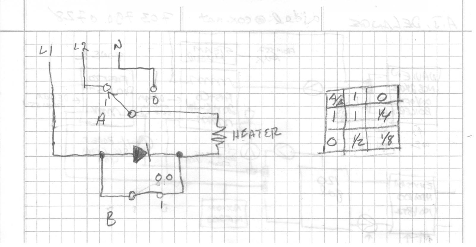
The following exquisitely simple circuit gives full, 1/2, 1/4 or 1/8 power depending on how the two switches are set. Switch A is a three way switch e.g. the sort that is used to turn lights on/off from more than one location and B can be an ordinary light switch. The diode should have a PIV of about 400 V and hefty enough to carry half the rms full load current. Could be an SCR with anode and gate connected together.

Voltages.jpg
 
Can't you manipulate the output using the outL & outH function? In my BK, I raise the outL to 60% & the outH down to 70% for a more steady boil. For my rims, I can do the % of output or use the outL & outH.
 
The following exquisitely simple circuit gives full, 1/2, 1/4 or 1/8 power depending on how the two switches are set. Switch A is a three way switch e.g. the sort that is used to turn lights on/off from more than one location and B can be an ordinary light switch. The diode should have a PIV of about 400 V and hefty enough to carry half the rms full load current. Could be an SCR with anode and gate connected together.

Definitely simple and would be highly applicable to a single vessel, manually controlled BIAB rig. For my application, I'll continue with PID/fuzzy!
 
Back
Top