• Please visit and share your knowledge at our sister communities:
  • If you have not, please join our official Homebrewing Facebook Group!

    Homebrewing Facebook Group

Rims control box

Homebrew Talk

Help Support Homebrew Talk:

This site may earn a commission from merchant affiliate links, including eBay, Amazon, and others.

Addiktion

Well-Known Member
Joined
Jul 28, 2016
Messages
114
Reaction score
26
Location
Orange County
So I've been looking around the forum and found a lot of good info. However I have a few questions. I have an 30A 240V dryer plug in my garage (3 wire) and want to hook up a spa breaker and convert to 4 wire in there to split 120v and 240v in my control box. My switches are 10A so I guess do I need contractors for all my switches? Also would 25A SSR handle the load? My PID is auberins sly-2352 and I haven't selected a heating element yet. I'm doing 5 gallon batches. I was going to mount a DIN rail two contractors a breaker but could use a little help. I don't want to waste money as I think I need a bigger relay? Any help I appreciate. I'm still working on a wiring diagram but any help there would be killer as well. Thanks
 
If you are only heating load is for the RIMS element, your supply circuit has more than adequate capacity.

For a recirculation heater for brewing 5 to 10 gallon batches, you probably will need a heating element in the 1500 to 2000 watt range. Your load current will be a little over 8 amps, So your 25 Amp SSR has more than adequate capacity to control the element.
 
Thanks for the quick responses. I've checked the electric brewery but haven't had time to read through it all. I'll give it a read. Thanks for helping out with my relay. I was about to buy another.
 
I would suggest waiting to buy parts until you have a finalized design. That avoids the risk of buying something that you can't use.

When you have your design complete, you can post it here to get it critiqued. Many eyes may catch something you overlooked.

If you need assistance with your design, just ask.

Brew on :mug:

This may be the best advice you will get.
 
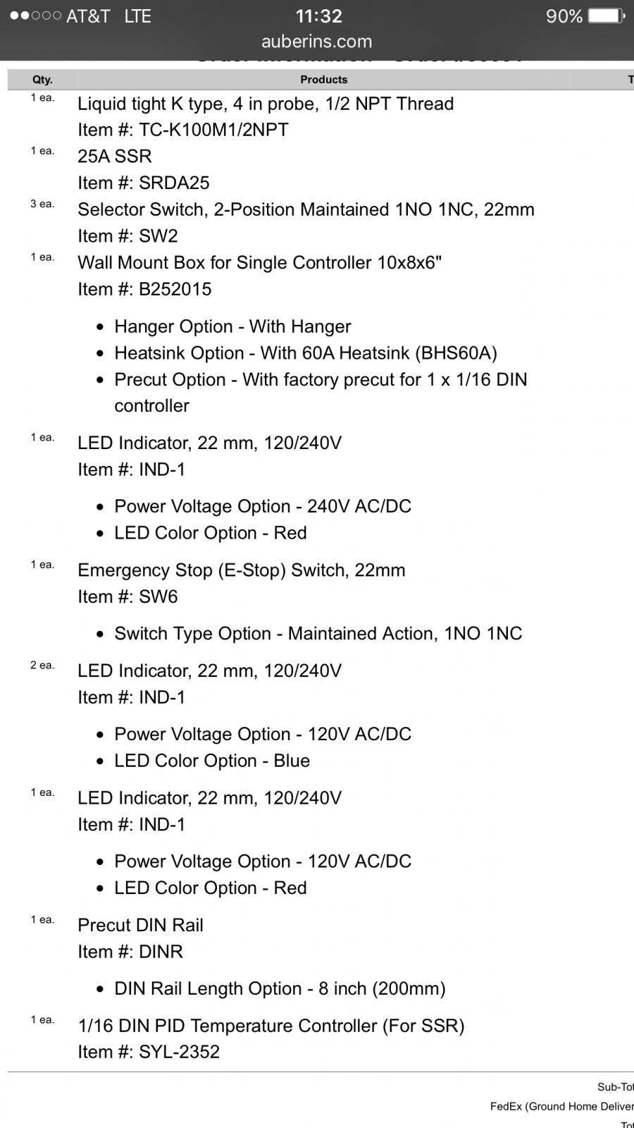
What I have now is attached so I don't have to type so much. I was thinking of adding to that: (2) 30A 240V contacters for power into the box and my element
(2) circuit breakers in the box and a spa breaker for source voltage. One breaker for my pump and the other for the element
(1) DIN rail terminal block kit. All from auberins

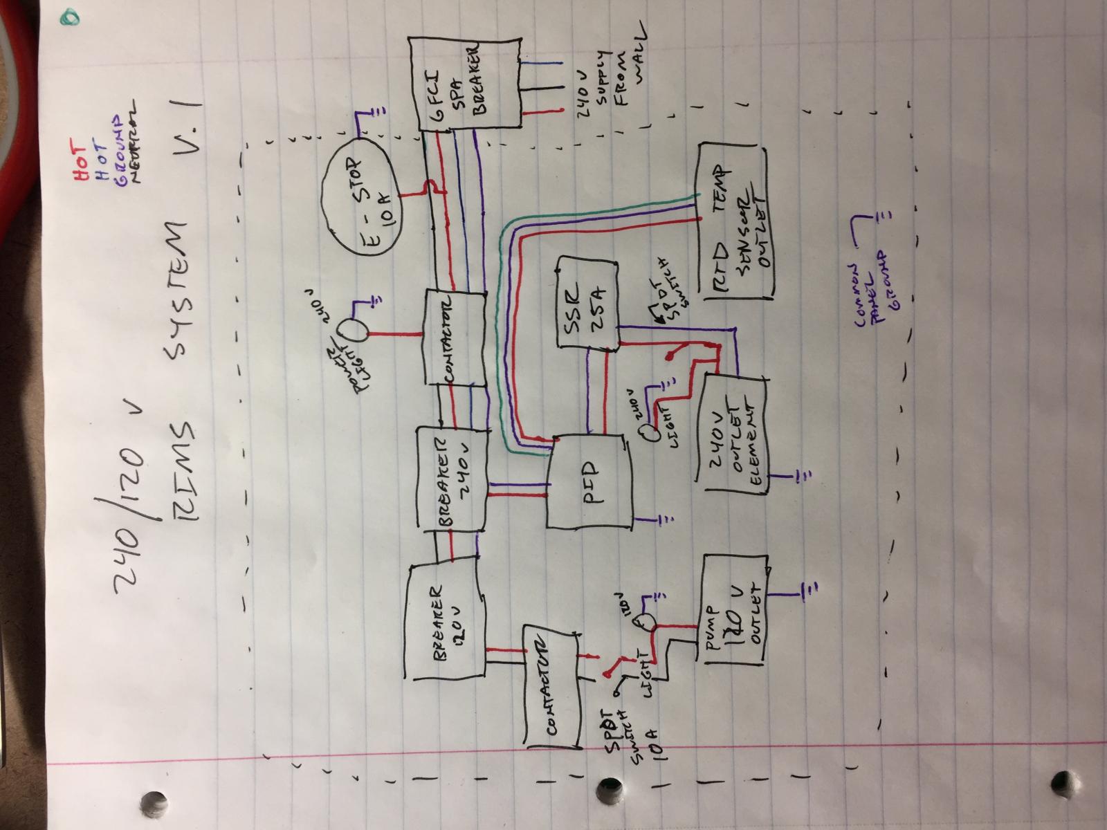
Then from the electric brewery a PID wire kit and a heating element with box and cord. Not sure if it's cheaper to go to Home Depot or order from them. I need to devise a plan for the low voltage side. I wanted to switch my element, pump, and main system power. I'll try and draw a diagram and send pics of my box so far. Thanks again in advance for any pointers in the right direction

IMG_0077.jpg
 
A couple comments.
1. The contactor for the pump is probably unnecessary. You can switch the pump directly with the SPDT switch.
2. Your drawing shows grounds and neutrals being switched through contactors and switches.
Grounds and neutrals should each be tied to their own common buss bars, and not be switched.
3.You may want to give your RTD wiring its own color code since it is connected to low level signals from the PID.

4. As you have it currently drawn at the moment, your drawing looks more like a functional one-line drawing, than a true wiring diagram. Nothing wrong with that. Lots of designs start as functional one-line drawings to illustrate a concept and then later evolve into a shop drawing that can be used to build from.
 
I have a few case grounds and I'm only familiar with cars/trucks for wiring. So this is a little new. But yeah I just wanted to lay something out on paper. How do I use 10A switches on a 30A circuit? I was thinking I needed bus bars but I started to get confused. Haha a lot more complicated then I first thought. However I start working on a more permanent diagram. Just never dealt with a neutral wire before.
 
I have a few case grounds and I'm only familiar with cars/trucks for wiring. So this is a little new. But yeah I just wanted to lay something out on paper. How do I use 10A switches on a 30A circuit? I was thinking I needed bus bars but I started to get confused. Haha a lot more complicated then I first thought. However I start working on a more permanent diagram. Just never dealt with a neutral wire before.

With an AC circuit, the neutral serves as the return path for current from a load, much like a ground connection does in an automotive circuit.

In an AC circuit, the purpose of the ground connection is not as a return current path in the circuit. The ground serves a completely different purpose.

The purpose of the ground connection is so that all exposed metal surfaces of the brewery, i.e. panels, conduit, piping, kettles, framework and everything else metallic can be bonded back to the ground conductor coming from the breaker panel.

The reason for grounding everything is to protect persons who may come in contact with a energized metal surface if it accidentally makes contact with the hot conductors from the panel. In a single phase residential panel, ground should never conduct any current when everything is wired and working properly.
In properly bonded equipment, contact of an energized conductor to ground anywhere should immediately trip a breaker in the panel, or blow a fuse.

The way you use the 10 amp switch to control the 30 amp circuit is to use the switch to control a contactor that is rated for 30 or more amps.

The switch is used to energize the coil of the contactor, and the contactor carries the higher current load.
 
One discrepancy in your design is that you show a PT-100 RTD temp sensor, but you actually purchased a type "K" thermocouple. Either will work with the SYL-2352, but they are wired differently, and the SYL has to be programmed for the type you are actually using.

Brew on :mug:
 
I swapped the K-type for an RTD sensor and I'm running one element and a pump. Not familiar with BIAB I just wanted to add a RIMS system to my current brewing. Thanks for all the help guys. I'm still going to work on a true wire diagram. I'll post it as soon as I can
 
From left to right I want, pump, element, system power. The fourth LED isn't 240v but can I use it for another purpose?
 
Close to my outlet. I have a gfci 120v outlet in my garage. I just wanted room to grow into all electric at some point

So the 240v is next to my work surface and 120 isn't. I have plenty of extension cords though. And my lack of knowledge on RIMS I just opted to go 240v. I've been thinking it may be easier to go 120 and cost me less money

image.jpg
 
Last edited:
With a 240 volt outlet, you have the capability to run 120 volt devices including heating elements. Lot of flexibility in how you deploy your panel and gear.
You can certainly run a RIMS with a 240 volt element. The key is using an element that is not too high of wattage for your application. Remember that ultimately the wattage determines the heat output, not the voltage.
That said, many folks build a RIMS for a 5 or 10 gallon capacity system using a relatively low wattage element. Running a 240 volt rated element at 120 volts can give you the benefits low watt density and optimal output power.
Having a 240 volt power source gives you the option for a scaleable system that you can expand later on.
 
My main supply can be 240 and I can just run all 120 inside my box right? I can just use the 240 and split it all on BUS bars right? Should I use a 120v element? I haven't even gone down the road of selection. But I think I'm going to use brewers hardware TC fitting.
 
You said that you have a three wire dryer outlet so you can't run 120v off that. You need a neutral.
 
I was going to split into 4 wires in a spa breaker. From what I gathered I believe it will still be GFCI if I go that route. Maybe not to code or standards but as long as it's safe I don't care.
 
I was going to split into 4 wires in a spa breaker. From what I gathered I believe it will still be GFCI if I go that route. Maybe not to code or standards but as long as it's safe I don't care.

Yes, if done correctly, you get GFCI coverage when deriving 4 wires from 3 with a spa panel. You want to minimize the (unbalanced) 120V loads in such a system, since the neutral current eventually ends up flowing thru your ground wire. This raises the "ground" potential above actual ground. The amount of the potential rise depends on the wire gauge, the run length, and the unbalanced 120V current. I wouldn't recommend running a 120V heating element on such a system. Most I would run is a Chugger type pump (two pumps if wired off different hot buses in the panel.

Brew on :mug:

Agreed.
If you are deriving a 4-wire circuit as described from a 3 wire there are a few limitations.
Keeping loads balanced between phases helps minimize issues.
Sticking to 240 volt rated devices like elements allows you to run smaller wire sizes too.
 
Thanks, good info. As of now it will be one chugged pump on the 120v and heating element 240v. I'll most likely keep this configuration for a few years before I make the full move to all electronic items and ditch propane.
 
Buy a 240v pump and wire things safely. Ground and neutral should only ever connect at the main service drop
 
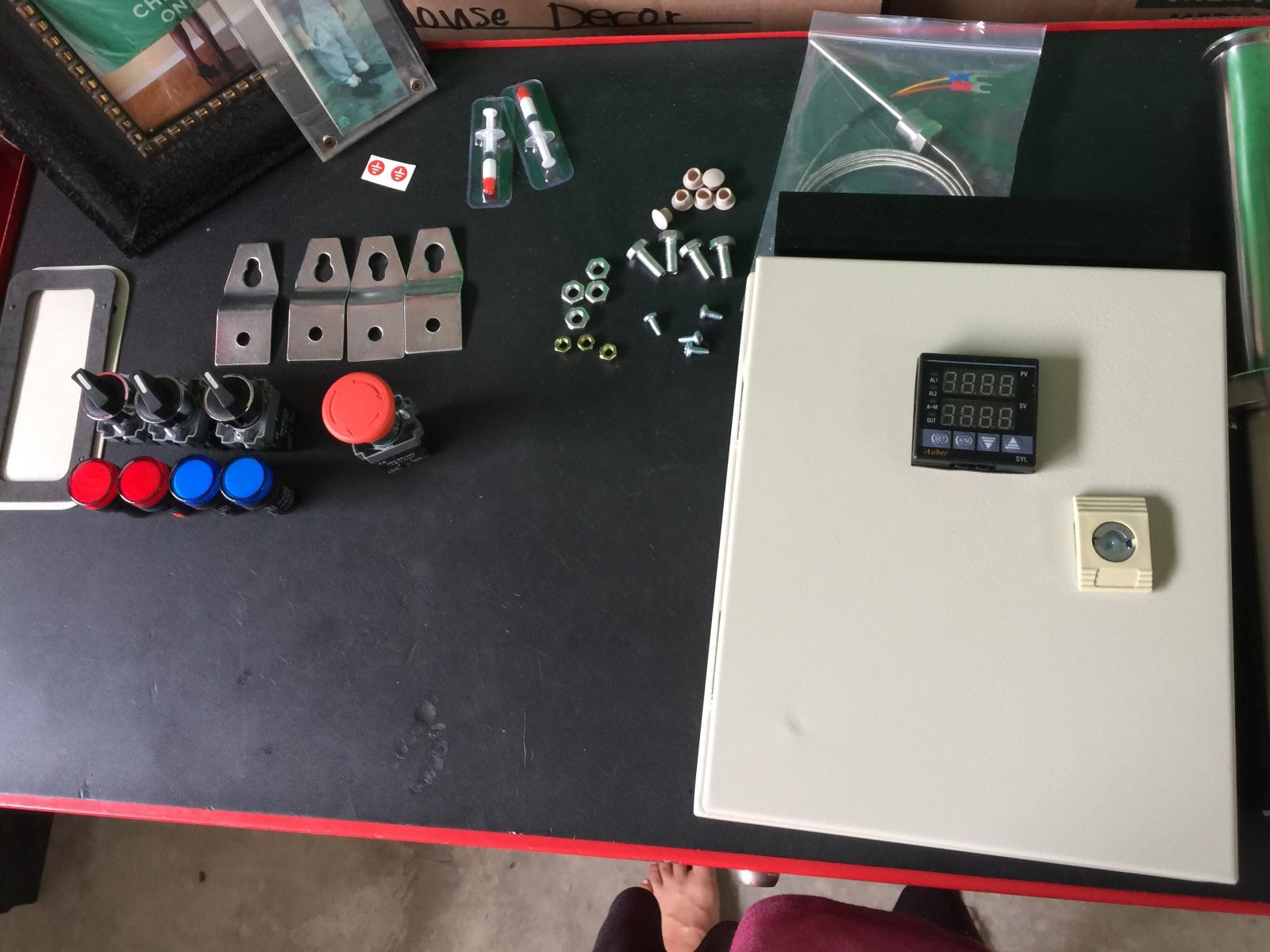
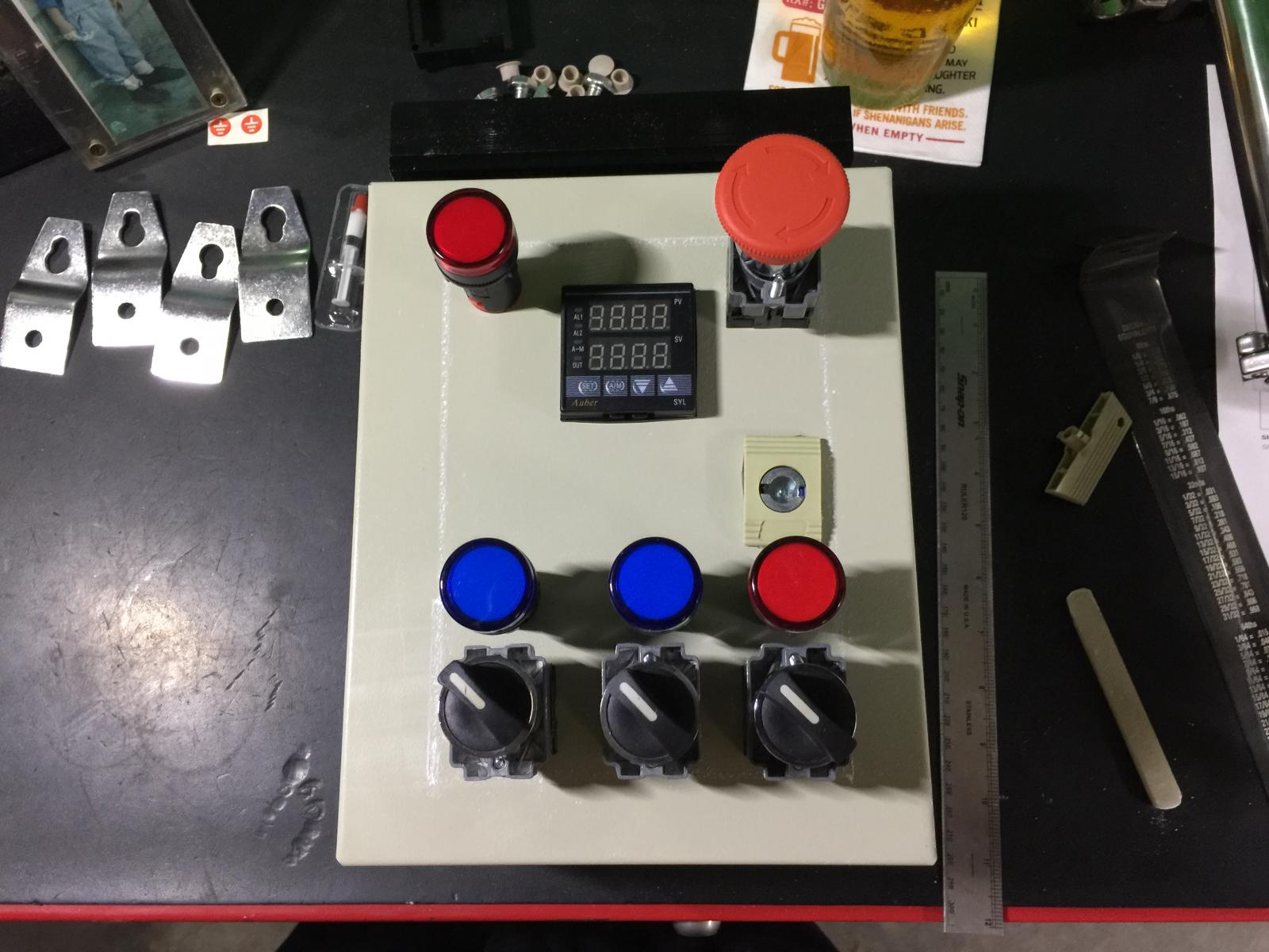
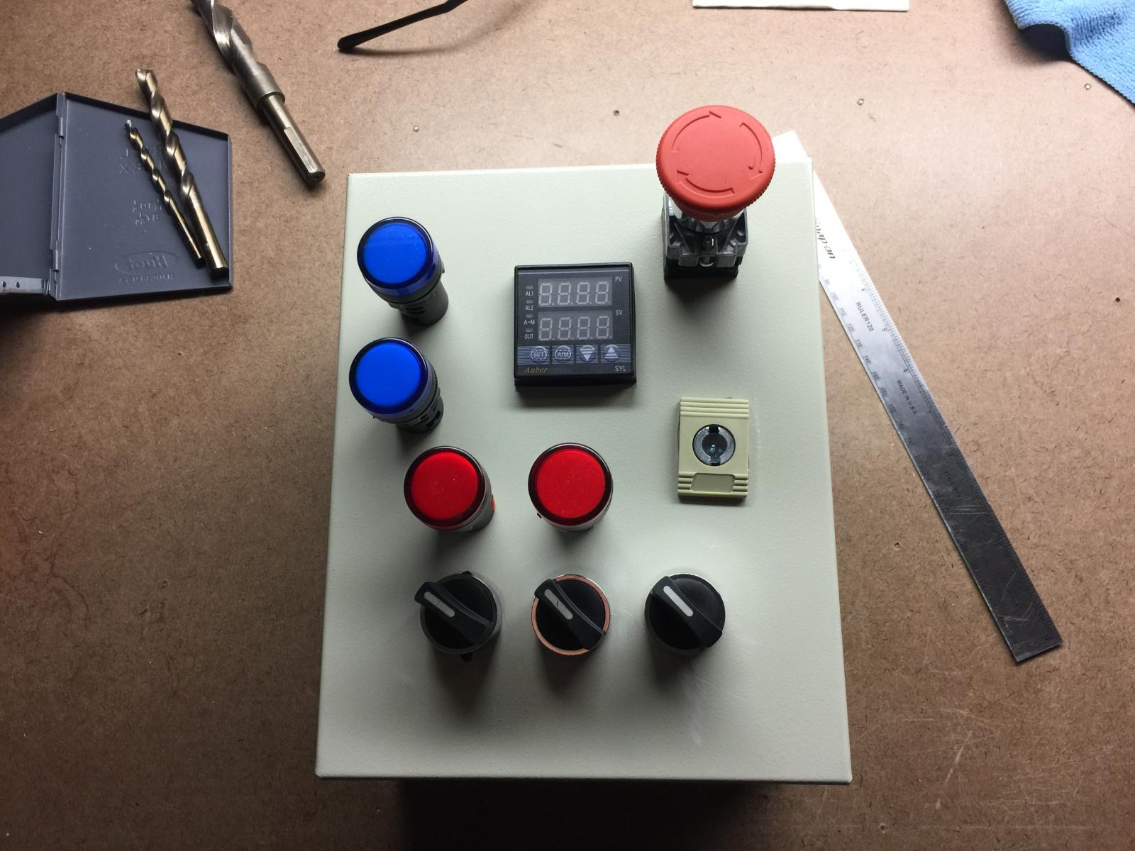
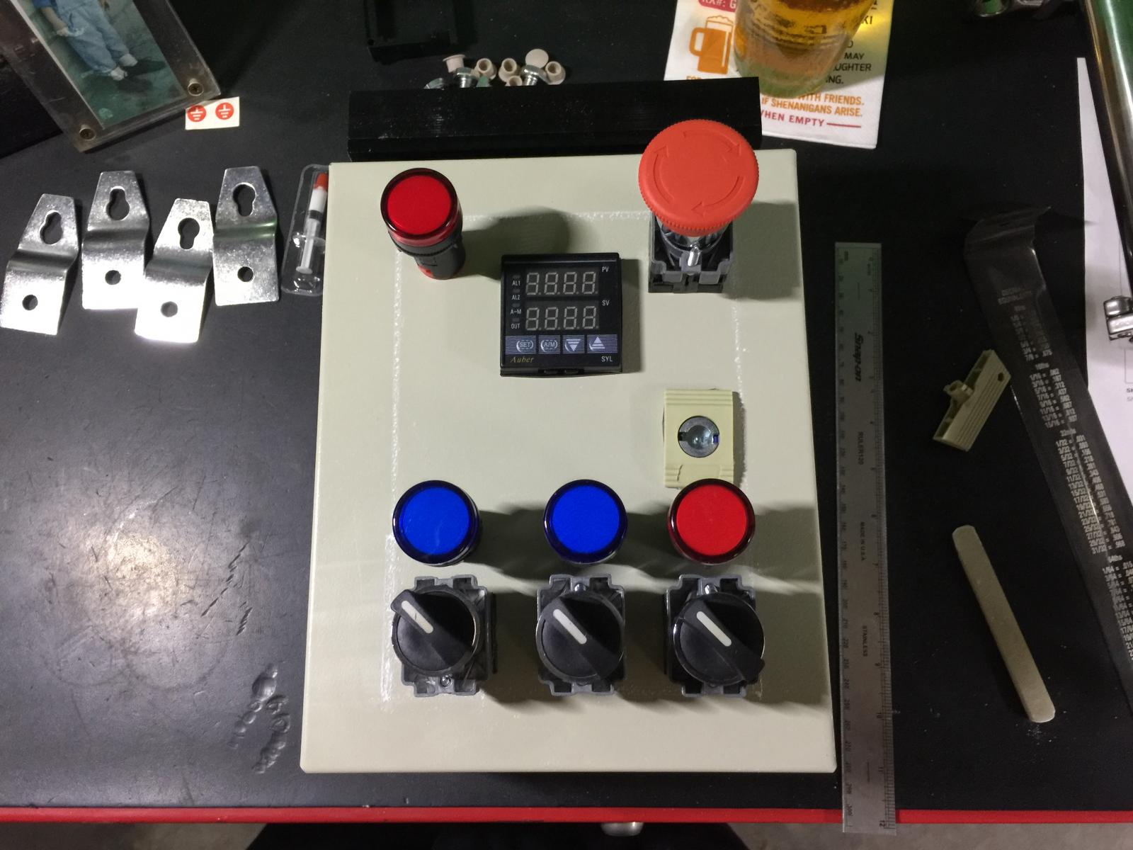
Well a few updates. I drilled my holes for the switches and set my light configuration. A little has changed given my useable space because the door lock and the water proof seal on the door. But this is my update. Waiting for the wire and the DIN rail to come in. Also going to paint the box. Notice I drilled the holes for the switch wrong on the one all the way to the left. Picture one is new layout picture 2 was original

IMG_0088.jpg


IMG_0083.jpg
 
Last edited:
Another update and a question. Can I use 120v leg to control my relay and PID but use the other side of the relay as 240v to heating element? And I got some parts in..

IMG_0090.jpg
 
Another update and a question. Can I use 120v leg to control my relay and PID but use the other side of the relay as 240v to heating element? And I got some parts in..

Can you describe in a little more detail what you have in mind? Normally when switching 240V, you have to switch both 120V legs, which requires both poles of a double pole relay or contactor. So, without more detail, I think the answer to your question is NO.

Brew on :mug:
 
I was thinking power comes in through the contacts and splits into separate legs in the box. Basically everything in the box is powered by 120v except the heating element. I was trying to figure out if I can use 120v on the PID and low voltage/amperage side of the SSR and 240v on the high side?
 
Back
Top