• Please visit and share your knowledge at our sister communities:
  • If you have not, please join our official Homebrewing Facebook Group!

    Homebrewing Facebook Group

Replacement firmware for iSpindel (GravityMon)

Homebrew Talk

Help Support Homebrew Talk:

This site may earn a commission from merchant affiliate links, including eBay, Amazon, and others.
I have done some updates to the gravitymon.com page and started to add a few relevant blog posts on the new gyro but also how to build an ESP32 based device. Gravitymon.com. More will come and if you have suggestions for topics let me know.

I have also added my own flasher to the site which from v2.2 also helps with configuring the wifi settings using the serial connection. All my projects will be adapted to use this approach in the future.
 
Gravitymon v2.2 is now released, available in my webflasher on gravitymon.com and brewflasher.

https://github.com/mp-se/gravitymon/releases/tag/v2.2.0

Gravitymon Gateway is also updated to v0.7 which adds support for Pressuremon as well.

https://github.com/mp-se/gravitymon-gateway/releases/tag/v0.7.0
Updated one of my spindels from 2.1 to 2.2 successfully. Also modified the voltage divider to 220k/220k. One small issue when changing/saving voltage factor: Displayed voltage does not update, unless I go Home and then back to Device-Hardware. This is with Firefox v140, have not tried other browsers. My correct Voltage factor ended up to be 2.06
 
Updated one of my spindels from 2.1 to 2.2 successfully. Also modified the voltage divider to 220k/220k. One small issue when changing/saving voltage factor: Displayed voltage does not update, unless I go Home and then back to Device-Hardware. This is with Firefox v140, have not tried other browsers. My correct Voltage factor ended up to be 2.06
Did you change it on the hardware page or use the "calculator" ?
 
s2 mini/ mpu6050. I am not sure what happens. Have tested 2.2 and 2.2.1. Both versions sends mqtt data while in config mode. Out of config mode: silence. I have also noticed that the s2 mini gets a bit warmer (around 35C) than in v2.1. Battery drains much quicker than normal. Checked the battery, internal resistance and capacity is ok. If I revert to v2.1, it works as expected again
 
s2 mini/ mpu6050. I am not sure what happens. Have tested 2.2 and 2.2.1. Both versions sends mqtt data while in config mode. Out of config mode: silence. I have also noticed that the s2 mini gets a bit warmer (around 35C) than in v2.1. Battery drains much quicker than normal. Checked the battery, internal resistance and capacity is ok. If I revert to v2.1, it works as expected again
Sounds strange, i have not tested the s2 mini in the latest versions, have you calibrated the voltage factor after upgrade? Does the device to into wifi setup mode? I will have a look when I get im back home again
 
Sounds strange, i have not tested the s2 mini in the latest versions, have you calibrated the voltage factor after upgrade? Does the device to into wifi setup mode? I will have a look when I get im back home again
Voltage factor calibrated - via the tool this time :) I did ota upgrades. It did not go into wifi setup mode. Wifi config was kept, so no need either.
No hurry. The unit I'm playing with is just for testing
 
Hello , folks !
Are you going to write RAPT PILL BLE compatible mode for transmission data ?
Anyone tried it ?
 
Fantastic project this.

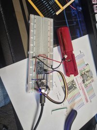
Currently putting together a build using an S3 supermini. Still learning coding with arduino so getting this going has exposed me to some new concepts (got stuck on build environments and adding a new board) but ive managed to create a new build environment for the super mini, flash it and get it reading from the gyro and charging using the supermini's built in charging circuit. Plan is to get it charging off a wireless charger and transplanted to a rapt pill.

Long term goal is to have it communicate with a temperature controller build via ble which will then forward the data via wifi or similar. Hopefully get some pressure monitoring (rough and ready qualatitive) via a cheap bluetooth tpms cap on the spunding valve.

Thanks for sharing this build. It is phenomenal.
20250912_094037.jpg
 
Fantastic project this.

Currently putting together a build using an S3 supermini. Still learning coding with arduino so getting this going has exposed me to some new concepts (got stuck on build environments and adding a new board) but ive managed to create a new build environment for the super mini, flash it and get it reading from the gyro and charging using the supermini's built in charging circuit. Plan is to get it charging off a wireless charger and transplanted to a rapt pill.

Long term goal is to have it communicate with a temperature controller build via ble which will then forward the data via wifi or similar. Hopefully get some pressure monitoring (rough and ready qualatitive) via a cheap bluetooth tpms cap on the spunding valve.

Thanks for sharing this build. It is phenomenal.
View attachment 884002
Thanks, feel free to check out my other brewing projects at gravitymon.com.
 
Last edited:
Having a look at getting a PCB fabbed up for the rapt pill using the S3 supermini. I'm going to do some digging (and ordering for some testing) as the documentation of the superminis is terrible. Given some of the boards have a great deal of flexibility on the pin assignments it feels like it should be possible to design one PCB which can use almost any supermini board. It might be possible to extend this to use the zero boards as well (probably easier to start with them as the documentation is much better and they seem less prone to QC issues) since all the boards follow the 5V/GND/3.3V pattern on the top corner with the superminis using the right hand side, the zero the left it might be possible to get a board to handle both by just turning it over.
 
Having a look at getting a PCB fabbed up for the rapt pill using the S3 supermini. I'm going to do some digging (and ordering for some testing) as the documentation of the superminis is terrible. Given some of the boards have a great deal of flexibility on the pin assignments it feels like it should be possible to design one PCB which can use almost any supermini board. It might be possible to extend this to use the zero boards as well (probably easier to start with them as the documentation is much better and they seem less prone to QC issues) since all the boards follow the 5V/GND/3.3V pattern on the top corner with the superminis using the right hand side, the zero the left it might be possible to get a board to handle both by just turning it over.
Its unlikely that you will be able to design one PCB that supports both the supermini and zero. The challenge with the supermini is that there is not one standard, there are differences between the manufacturers and the zero board has 18 pins instead of 16pin. The zero boards seams to be more common across manufacturers.

Some of the GPIO are not usable so finding a overlapping match would be hard.

The downside of having a board up-side down is that the reset and boot buttons will be impossible to use....

I'm currently testing out my first prototypes for the esp32c3 zero and I received the boards for both PILL casing and iSpindel PET yesterday.

I decided to focus on the zero since they seams to be easier to source across the globe. But more on this topic once I have built the first prototypes.
 
Aye. I know what you are saying. The zero boards appear to be much more consistent, its part of the reason im looking at them as well as the super mini boards.

When i said flipping the board I mean flipping the pcb rather than the development board. This should keep the reset, boot and led visible (dev board still in correct orientation) whilst flipping the voltage pins.

Looking forward to seeing your prototypes when they are ready.
 

Latest posts

Back
Top