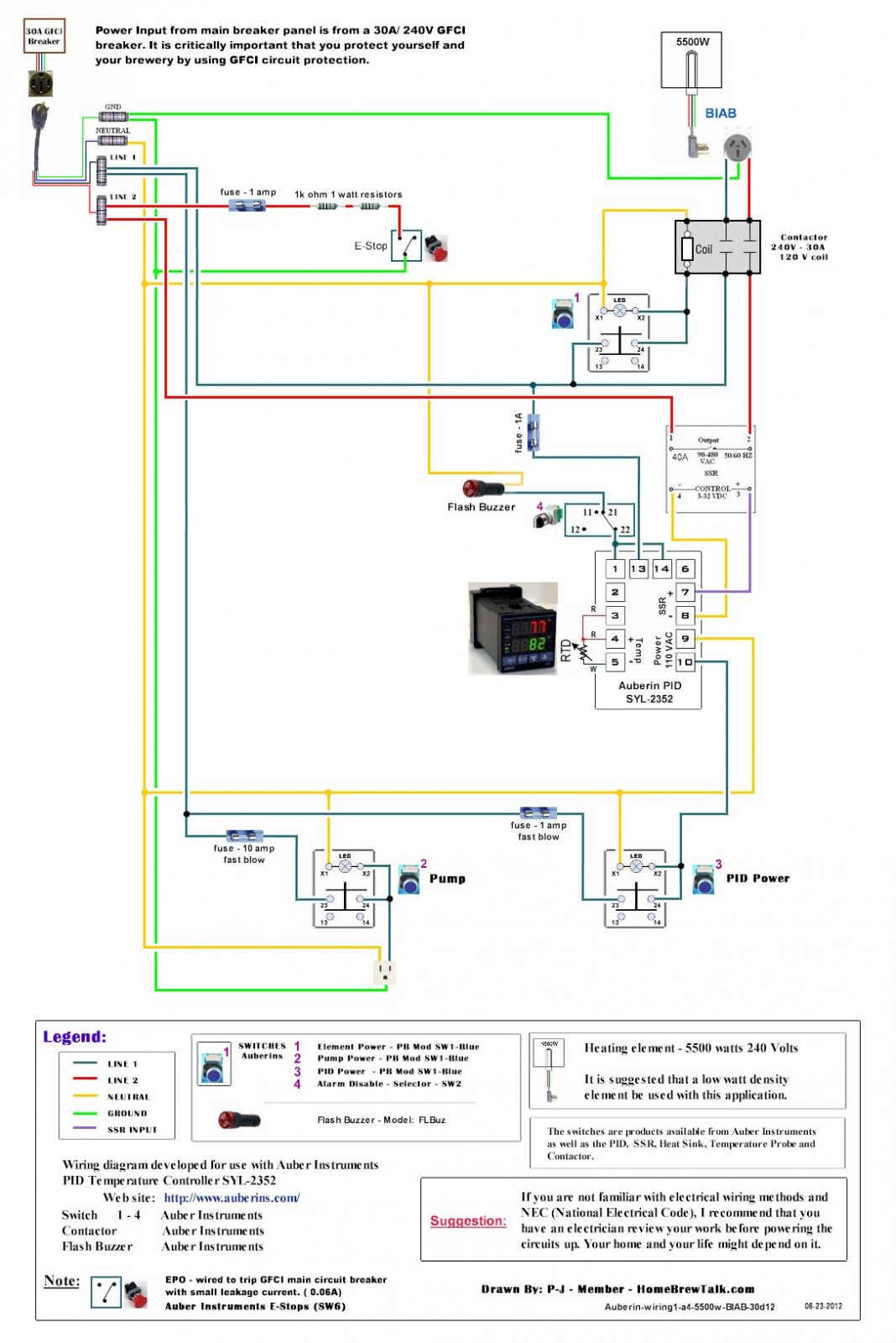
Question on P-J Schematic wiring

Homebrew Talk - Beer, Wine, Mead, & Cider Brewing Discussion Forum

Help Support Homebrew Talk - Beer, Wine, Mead, & Cider Brewing Discussion Forum:

This site may earn a commission from merchant affiliate links, including eBay, Amazon, and others.

nobadays

Supporting Member
HBT Supporter
Joined
Apr 4, 2016
Messages
758
Reaction score
2,949
Location
Payson AZ/Colorado
Back from a road trip and beginning to wire my control panel. (Build thread https://www.homebrewtalk.com/showthread.php?t=582004 )

Attached is the Schematic I am using with a slight alteration - adding one more pump. As I review the schematic it seems to me that one (1) leg of the 240v to the element will be on as soon as the switch to the element is turned on. (This energizes the contactor allowing the "blue" leg to feed power to the element?) The other leg is controlled through the PID/SSR/Contactor... Am I missing something or is this correct?

Thanks in advance!
Don
Primary: nothing
Secondary: nothing
Bottled: Oatmeal Stout, APA and Rye IPA

Correct One-Auberin-wiring1-a4-5500w-BIAB-30d12.jpg
 
It's OK but I prefer that the red line feed the input leg of the contactor and output of the contactor feed T1 of the SSR. That way there is no power on the element or the SSR when the switch is OFF.
 
Poobah58... I'm not following?? I agree it would be better to not have power to the SSR or element when the switch is off. That said I don't see how you are suggesting the "re-wire" can you be more descriptive?

I think you are saying to use the switch to power the SSR? but how would you re-route the wires to do so... sorry...I can wire a house but for some reason this is confusing me!

Thank you!
Don
Primary: nothing
Secondary: nothing
Bottled: Oatmeal Stout, APA and Rye IPA
 
OP - That is correct, one leg will be hot at all times when the contactor is closed. The other hot leg is switched by the SSR. Even if you install an SSR on both hot legs, you'll still get some residual voltage at the plug because SSR's leak a little. Just remember that when the Contactor is closed/energized, that there is voltage on one leg.
 
On your second question, wire the SSR in between the element and the contactor instead of ahead of the contactor. My scanner is on the fritz so I cant show you what I mean in a drawing, sorry.
 
atoughram...poobah58... Thank you for the input!

If I am getting this right, you (both) are saying run the "red" lead directly to the contactor then wire the SSR down stream -the element side- of the contactor back into that "red" leg. In essence then I would still have 1 leg - the blue one - feeding the element the second the switch is turned on but the second leg - the red one - would then be energized and controlled/powered by the SSR which is controlled by the PID. Correct?

Does that put undue stress on the SSR or does it not matter? I thought the SSR was "upstream" of the contactor for that reason.

I will assume...maybe wrongly... that having one leg to the element hot all the time keeps the kettle contents warm/hot, then the other leg is used to regulate mash/boil temps?? But if this is the case it would seem that the element could possibly still be putting out sufficient heat to raise the mash temperature beyond where I might want it - true/false??

Trying to get a handle on this!

Thanks!
Don
Primary: nothing
Secondary: nothing
Bottled: Oatmeal Stout, APA and Rye IPA

Current flows thru a loop. If you cut the loop at any point, current flow stops. If there is no current flowing, then no power is being delivered.

Brew on :mug:
 
Thanks Doug for your input!

I have done a fair share of house/shop/commercial wiring so kind of sort of have a handle on how current flows... it is these electronic components, {SSR, contactor specifically} that I just have no experience with. I worked years for a municipality and have stood over the shoulder of controls electricians as they worked in pump panels, etc. but I never touched that 440V stuff! (We won't talk about the 1700V that took my left arm off 26 years ago in an accident :D )

I have much respect for PJ and all the work he did providing schematics for folks on here... and have seen that you also are providing some great schematics yourself - good on you!!

So maybe you can answer a question... Why did PJ choose to only switch one leg with the contactor through the PID/SSR? The element switch immediately supplies 120v to the element (approx 1375w) when it is closed leaving the other leg then controled by the PID/SSR to bring the 5500w element to its full potential. Logic - my probably faulty logic says switch the contactor coil via the PID/SSR and eliminate any power going to the element until the temp probe calls for it.

My thinking is that it was done this way to prevent such a drastic load being applied to the components each time the element kicks on and off to regulate temperature. And that the 1375w going to the element though sufficient to raise the temp of the kettle - even to a boil - would take so much time that it is not a huge factor weighed against the stress on the system by switching both legs simultaneously. Correct?

I PM'd another forum member who built a nearly identical system and he says he has no problem using this design, in fact says it operates flawlessly through the mash and then into the boil. So I will proceed with the wiring but I'm curious!

NOTE... sort of unrelated question... Am I correct that the contactor is non-directional? Meaning I can put the input/output leads - both for the coil and the main switch - on either end/side? (I realize the coil requires a hot and a common, whereas the main switch is 2 hots in 2 hots out)

Thanks!
Don
Primary: nothing
Secondary: nothing
Bottled: Oatmeal Stout, APA and Rye IPA
(2.5 cases of homebrew left...gotta get this rig up and running!)
 
...

I have much respect for PJ and all the work he did providing schematics for folks on here... and have seen that you also are providing some great schematics yourself - good on you!!
Unfortunately, P-J isn't very (or at all) active on HBT anymore (his last post was about 11 months ago.) I'm trying to do what I can to fill in the large void left by P-J's absence, but certainly will not be able to fill his shoes.

So maybe you can answer a question... Why did PJ choose to only switch one leg with the contactor through the PID/SSR? The element switch immediately supplies 120v to the element (approx 1375w) when it is closed leaving the other leg then controled by the PID/SSR to bring the 5500w element to its full potential. Logic - my probably faulty logic says switch the contactor coil via the PID/SSR and eliminate any power going to the element until the temp probe calls for it.
Yes 120V is supplied to the element when the contactor is closed and the SSR is off, but since the off SSR prevents any current from flowing, there is no power going to the element. If you measure the voltage between the two hot connections at the element when the SSR is off, you will read very close to 0V. If you measure the same points with the SSR on, you will measure about 240V. The element is just a resistor. When there is 0V difference between the ends of the resistor, there is no current flowing in the resistor, and no power is being dissipated by the resistor. When there is a voltage difference between the two ends of a resistor, then current is flowing thru the resistor, and power is being dissipated by the resistor. The power is given by I * I * R, where I = current and R = resistance (if I = 0, then power = 0.) Read the analogy between current and water flow, and pressure and voltage, that I posted here. It may help you understand.

My thinking is that it was done this way to prevent such a drastic load being applied to the components each time the element kicks on and off to regulate temperature. And that the 1375w going to the element though sufficient to raise the temp of the kettle - even to a boil - would take so much time that it is not a huge factor weighed against the stress on the system by switching both legs simultaneously. Correct?
No, the SSR switches between 0 power and full power. There is never any partial power delivered to the element.

You don't want to actively control the element with a contactor, as it would be switching about 60 times a minute with a standard PID, and up to 1800 or 3600 times a minute if using a controller like the DSPR110. That much switching will wear out the contactor very quickly, and be very noisy.

NOTE... sort of unrelated question... Am I correct that the contactor is non-directional? Meaning I can put the input/output leads - both for the coil and the main switch - on either end/side? (I realize the coil requires a hot and a common, whereas the main switch is 2 hots in 2 hots out)
Correct, the contactor is non-directional, you can connect load or supply to either of the contacts. Remember, we are working with AC, so current flows back and forth in both directions, so the contacts have to be non-directional. A 120V coil requires 1 hot and 1 neutral, but it doesn't matter which is connected to a particular end of the coil. A 240V coil would require 2 hots to be connected.

Brew on :mug:
 
"I see" said the blind man as he picked up his hammer and saw! Thank you so much for this explanation! I DO see! My assumption was correct that it is due to undue stress being put on the contactor to switch the coil - I had no idea that the PID turned the element on and off 60 times a minute - but knew it would be switching the element on and of pretty often. That said my reasoning was WAY off! After reading this post and the one you referenced I finally get it that the 2 120v legs off the contactor are needed to complete the circuit!

I guess what I really didn't/don't understand is how the element worked. I get the "flow" thing but I couldn't envision 2 hot legs "completing" the flow for that circuit. I am too used to 1 (or 2 if 240v) hot leg/s, 1 common leg and you have a complete circuit...switch the hot side and it will break the flow. I guess my knowledge of electrical theory is lacking, even after some more research - CT transformer so no neutral is needed huh? - too old to learn now!

Thank you again for helping me to see what is going on, even if I don't understand all the theory behind it! I started bending and attaching wires today!

Don
Primary: nothing
Secondary: nothing
Bottled: Oatmeal Stout, APA and Rye IPA
(2.5 cases of homebrew left...gotta get this rig up and running!)
 

Latest posts

Back
Top