
Esmitee
Well-Known Member
I didn't want to hijack Mike's thread anymore so I moved the discussion here.
It's started from this post.
https://www.homebrewtalk.com/forum/...-herms-240v-30-amp.622007/page-4#post-8213099
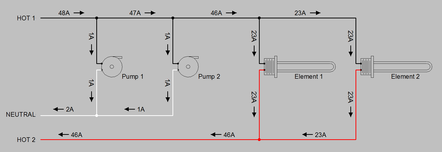
OK, here's the drawing. It's a (not unrealistic) representation of current flow in a50A control panel. I left out all of the switches, contactors, PID's, lights, etc. The arrows show current flow direction during 1/2 of the AC cycle. During the other 1/2 of the cycle current flow is in the opposite direction.
Ok Doug, so if I interpret your diagram correctly. I should place the CT on my RED hot line before my main contactor because I have the most "loops" on this side.
I'll explain how my power is distributed in the picture.

# 1 is a 6 AMP breaker supplying power to the door. Pids, switches, key switch and lights.On the RED Leg
# 2 is a 5 AMP fuse supplying tower to pump # 1. On the RED leg
# 3 is a 5 AMP fuse supplying power to just the case fan and the AMP/VOLT meter. On the BLACK leg
# 4 is a 5 AMP fuse supplying power to pump #2. On the BLACK leg
So I guess I should put the CT on the RED LEG because the RED LEG would have the most loops?
I'm guessing, the way I have the power separated like this, and putting the CT on the RED LEG, the V/A meter will not read the power on the BLACK leg?
It's started from this post.
https://www.homebrewtalk.com/forum/...-herms-240v-30-amp.622007/page-4#post-8213099
OK, here's the drawing. It's a (not unrealistic) representation of current flow in a50A control panel. I left out all of the switches, contactors, PID's, lights, etc. The arrows show current flow direction during 1/2 of the AC cycle. During the other 1/2 of the cycle current flow is in the opposite direction.
- The wire segment with 48A is part of 4 loops
- The wire segment with 47A is part of 3 loops
- The wire segments with 46A are part of 2 loops
- The wire segments with 23A are part of 1 loop
- The wire segment with 2A is part of 2 loops
- The wire segments with 1A are part of 1 loop
Ok Doug, so if I interpret your diagram correctly. I should place the CT on my RED hot line before my main contactor because I have the most "loops" on this side.
I'll explain how my power is distributed in the picture.
# 1 is a 6 AMP breaker supplying power to the door. Pids, switches, key switch and lights.On the RED Leg
# 2 is a 5 AMP fuse supplying tower to pump # 1. On the RED leg
# 3 is a 5 AMP fuse supplying power to just the case fan and the AMP/VOLT meter. On the BLACK leg
# 4 is a 5 AMP fuse supplying power to pump #2. On the BLACK leg
So I guess I should put the CT on the RED LEG because the RED LEG would have the most loops?
I'm guessing, the way I have the power separated like this, and putting the CT on the RED LEG, the V/A meter will not read the power on the BLACK leg?
Last edited:


![Craft A Brew - Safale S-04 Dry Yeast - Fermentis - English Ale Dry Yeast - For English and American Ales and Hard Apple Ciders - Ingredients for Home Brewing - Beer Making Supplies - [1 Pack]](https://m.media-amazon.com/images/I/41fVGNh6JfL._SL500_.jpg)


")

