PID question

Homebrew Talk - Beer, Wine, Mead, & Cider Brewing Discussion Forum

Help Support Homebrew Talk - Beer, Wine, Mead, & Cider Brewing Discussion Forum:

This site may earn a commission from merchant affiliate links, including eBay, Amazon, and others.

Owly055

Well-Known Member
Joined
Feb 28, 2014
Messages
3,008
Reaction score
686
I just got a PID controller. I have the configuration settings worked out. Output options are internal relay (5 amp), SSR, or Triac, as well as an alarm circuit with the same outputs. I'm configured for heating, and for internal relay, units are F, and the setpoint at the moment is 195F.

No thermocouple is connected at the moment. Is it normal that the internal relay should be open circuit unless a thermocouple is connected? I assume that is why I have no continuity on my relay connectors.

I will probably only operate using Proportional, and using the hysteresis setting. I don't see any particular benefit in using Inductive and Derivative functions for my purposes.
 
It is normal to have an open circuit. Why would the PID close the contacts calling for heat; when it doesn't
know (NO THERMOCOUPLE) what the current temp is? The PID should be displaying a no thermocouple error
of some kind. If possible, purchase an RTD?
 
If you don't have a thermoprobe yet but can obtain 100-300 Ohm potentiometer - you can connect it instead of a thermoprobe. Set your PID to work with PT100 probe. Then pot's knob rotation will simulate temperature change.
 
I've got everything configured..... I think, and still get no change in points open / closed state with the thermocouple connected. Seems to read the TC about 10 deg high....It will start out close to the reading my other meter shows, and just keep reading higher and higher until it settles about 10 deg over (adjustable offset), but I can move the set point above or below the temp reading and I still get no change. What I do have is about 24vdc reading across these two terminals......... regardless of temp and set point. 24 VDC 20ma is the ouput for running an SSR..... but it isn't set for SSR, nor does it switch when I move the setpoint..... I am of the opinion that it's a wonderful Chinese product that isn't worth even what I paid for it.............

H.W.
 
What exactly your PID model and could you post a pics with your wiring and/or schematic diagram?

It's a MYPIN Temperature Controller Model TA4-SNR Made in China. The instruction sheet is a bit difficult to decipher as it was written by a Chinaman who didn't have a really good grasp of English. Here is all I have to work with.... This is a reduced size link from Dropbox leading to the instruction manual.......

https://db.tt/7ATqY7tK


H.W.
 
I did use a bunch of Mypin Ta4 all of them was working fine. Most likely something wrong with settings or wiring. Have you ever seen "out ".indicator to be lighted?
 
Out1 indicator is on steadily.......... It is very slow to come up to it's reading and stabilize, and the reading tends to be about 10 deg F too high I'm using a blade type thermocouple with two very short jumpers with slide on spade terminals between the TC and the PID..... Wires are about 3" long solid copper with crimp fittings on the spade ends...... There shouldn't be any significant resistance here......... but perhaps it's enough to throw things off. In any case you can adjust the offset to make it read correctly, but you can't get the relay to function. At the moment I have the set temp about 30F higher than the temp shown, the unit set for heating, the output set (cel) set for 020 (relay). It will give me about 15 vdc on the output connection........... continuity doesn't change as it should for relay. I can move the setpoint, and the voltage will go away. That says that it is shifting something........ not the relay though. The setting is relay (010 or 020). The setting for SSR SCR is 001. Interestingly it won't let me change the middle digit now........ though previously it did. It's just flaky.............. It also doesn't always hold settings when shut off.

There's really nothing to be wrong with wiring........... The power is obvious pins one and two, and the TC connection is 7 and 8 (just opposite)...... The polarity is well marked for the TC connection. If you reverse them, the reading is way out of whack. Those are the only two connections I have on it so far. 3 and 4 should be the output relay, and I'm using the VOM to test continuity and voltage there. I've tried hooking L1 to 3 as it should be, to see if the relay will trip with power to it... as it should...... still no joy.

H.W.
 
OK now I understand an issue. Mypin is good PID but it doent have an universal output. It can be either relay or SSR control.
Your version (Ta4-SNR ) has voltage output (24v) only to drive an SSR. TA4-RNR has a relay output only. Setting output type ftom service menu doesn't work since you PID has no mechanical relay inside. (Actually it has but for alarm output only)
 
The info sheet makes it look like it does have an internal EM relay........ But looking at the model number key it obviously does not......... Also the print on the side does not show one. The fact remains that it doesn't switch the 24V on and off. I hooked an LED to it, and it seems always to be on.
The 24 vdc 20ma output is too low to run anything but a mosfet, triac, or SSR. I'm comfortable using mosfets..... I've never used a triac before though I have half a dozen or so on hand. Problem with a mosfet is I would need a DC supply to make it work and use a dc coil relay..... that just complicates things. Looks like I can gate a triac with the 24 vdc signal, and switch AC to run a power relay. guess I'll have to haul out the soldering iron and go to it!

H.W.
 
OK now I understand an issue. Mypin is good PID but it doent have an universal output. It can be either relay or SSR control.
Your version (Ta4-SNR ) has voltage output (24v) only to drive an SSR. TA4-RNR has a relay output only. Setting output type ftom service menu doesn't work since you PID has no mechanical relay inside. (Actually it has but for alarm output only)


THANKS FOR THE HEADS UP...........I didn't realize from the documentation that I didn't have an internal relay..... looking at the model number breakdown, I see you are right.

Having a dozen or so 16 amp triacs, I decided to use one in lieu of an SSR. It took a little doing to get the bias figured out......... two tries actually. At first I had it set to 001, which apparently is a "current" output, where 000 is a voltage output. The current controlled output required a different bias to work. I switched to 000, and the bias on the triac worked as it should.

I connected the triac to a 115vac coil contactor, and it would work then. The default P and I settings made the thing chatter on and off as it approached the set value..... which would be OK if you were using an SSR......but not an electromagnetic contactor. I had to switch P and I completely off, and set the hysteresis to about 3. Now it will allow it to drift 3 deg before kicking on. Since I have quite a few triacs, I decided that I will dispense with the contactor, and parallel several triacs so I have a good margin of current capacity.... at least double. Mount them to a heat sink, and I've got an SSR for about a dollar's worth of semiconductor parts and a piece of aluminum.

When I get this hooked up to the heating element, I'll play with proportional and integral settings.....I'm not quite sure how to optimize them.

The slow display is frustrating..........It should instantly read the thermocouple temp, but in the end it won't matter much once it stabilizes.

H.W.
 
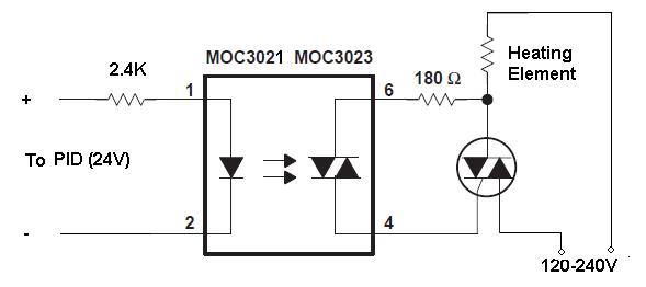
It's highly not recommended to connect SSR output directly to triac. Much better to use an ouptocoupler like MOC3021-3023

moc.jpg
 
I connected a triac to the output..... It works fine. I had problems with the default settings for P and I initially as I was driving a contactor. As it approached temp, the contactor would start rapidly cycling off and on...more off as it got closer........... Which is what it is supposed to do. The last thing I want is a contactor slamming the points open and closed rapidly, so I shut P and I off........... I then decided that there is no reason to use a contactor when I have a bag of triacs rated 16A each. So I hooked 2 in parallel and reset the P and I settings to defaults............ It simply doesn't work at all under P or I or P & I now??? The output just stays on, no matter what the temp. Also when I set it to Autotune, it does the same thing. Turn everything off and set the Hysteresis setting for 3 and it operates perfectly.... allowing a 3 degree variation before kicking on. Unless autotune is activated...........The thing is unpedictable!!

H.W.
 
It's highly not recommended to connect SSR output directly to triac. Much better to use an ouptocoupler like MOC3021-3023

This is the first time I have used a triac........ I did it more or less the way you drew it, though I put my resistor on the gate instead of the source...... or whatever they call it. Thinking like a Mosfet. I used an 820 ohm resistor for my bias resistor. Started high, and kept using smaller ones until it worked well. I'm not sure how to figure bias.......... but this worked fine.

Others have warned that this wasn't a good idea........... I presume simply using a very low current fuse...... 10ma or something, would protect the PID adequately. The danger would seem to be if the triac shorted and you had full 115vac across the output......... When I board mount it, I'll put a fuse holder on it. It's not like I'm dealing with high dollar stuff. A $25 PID (incl shipping), and a couple dollars worth of triacs, and a resistor worth a few pennies. The settings listed on the sheet include SSR and SCR. I'm set for SCR.... a triac is just a pair of SCRs, so I assume that they intended that it be used that way...........

H.W.
 
Back
Top