• Please visit and share your knowledge at our sister communities:
  • If you have not, please join our official Homebrewing Facebook Group!

    Homebrewing Facebook Group

Open your panel and show me whats inside

Homebrew Talk

Help Support Homebrew Talk:

This site may earn a commission from merchant affiliate links, including eBay, Amazon, and others.
kal said:
You probably mean my post a few posts above: https://www.homebrewtalk.com/f170/open-your-panel-show-me-whats-inside-438542/index3.html#post5611443 Why? Because it looks cleaner and may make part replacement simpler. Worth it? That's up to you. Kal

Of course when I'm on the iPad having to rely on crappy slow 3G internet. Sorry I couldn't see images so well.

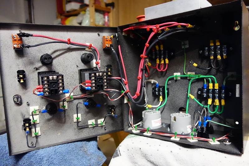
I think it looks so clean plus you can make some cool colors for the mounting plate. Looks like I'm going to the store for some color choices and grommets.
 
Mine so far and wow did I underestimate this build! So much more to it then I thought it was going to be but a lot of fun building this system. Hopefully everything works out when I go to test it.


DSC01091 by Ludahchris, on Flickr
 
50 amp BCS 460, SSR's for each leg of 240, spare SSR already mounted and hooked to unused output of the BCS for future expansion or in case of SSR failure, I could quickly run some jumper wires to get back to business. The unit under the wall wort is a 90 volt D.C. power supply for my pumps.

Gunmetal, do you have any large pics to get a better look?

Thanks,
Trent
 
I'm controlling my RIMS tube with the PID controller and recently added a PWM board and second SSR to control my HLT and BK.

I used a mix of new and used parts and power it all with a 50 A GFCI 220 volt circuit.

Its simple yet flexible and functional,

DSCN3289 (Small).JPG


DSCN3293 (Small).JPG


DSCN3291 (Small).JPG
 
Prices of the different plug/ cord and outlet combinations can be expensive.

This was a relatively cost effective alternative. Cord/plug was $17. Receptacle and box were $7.
 
So who is using DIN rails. I have all my components ready and am going to hopefully (fingers crossed) start on the panel this weekend. I have all din mount items.
Is it better to mount running top to bottom or by elements or by random order.
What have you found that works best? (I'm sure there is a thread for this but it is beady-bye time!

There are a ton of theories on panel layout. Not sure there is one right answer. DIN rail is nice in that it ensures that everything is neat and straight (assuming you mount the rail that way).

Before I drill the first hole, I will lay parts out in the panel to see how things look fit. Think about how I will route field wiring to the components.

Don't hesitate to try different trial layouts before committing to one. Think about all the things connecting to the panel from the outside and how you can keep wire paths direct and neat.

One general guideline, and its only a guideline, is to keep power devices and power wiring in one area of the panel and low level and control devices in another area.
 
Before I drill the first hole, I will lay parts out in the panel to see how things look fit. Think about how I will route field wiring to the components.
I am doing just that. I like it a couple of different ways.
One general guideline, and its only a guideline, is to keep power devices and power wiring in one area of the panel and low level and control devices in another area.
That's a good idea. I didn't think about that but it ends up that is how it will workout in the end.

I did a little sample wiring this morning. I think this will look great. It took me 10 minutes to place the first 2 wires though. YIKES! It's a full day followed by a sixer.
 
I cut my pid controller in half so that it fits in a thinner case. The sensor cable was later routed through one of the cable glands.

20130612_223215.jpg
 
triskelion said:
I cut my pid controller in half so that it fits in a thinner case. The sensor cable was later routed through one of the cable glands.

That's pretty crazy. I never thought about braking other pid apart.
 
Back
Top