New Rig Plans

Homebrew Talk - Beer, Wine, Mead, & Cider Brewing Discussion Forum

Help Support Homebrew Talk - Beer, Wine, Mead, & Cider Brewing Discussion Forum:

This site may earn a commission from merchant affiliate links, including eBay, Amazon, and others.

BrewSpook

Well-Known Member
Joined
Dec 6, 2008
Messages
447
Reaction score
9
Location
Richmond, VA
Hey guys - just wanted to run my system design by everyone and look for input.

I have been brewing on a 2 vessel No-Sparge (Continuous Sparge) system for almost 4 years now and I love it. I want to automate as much as possible so I can evetually brew from work using a web interface. I just built the first iteration of my stand this weekend and brewed on it - needs a few modifications, but worked pretty well.

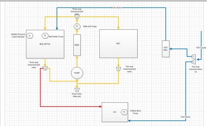
Here is the plumbing diagram I came up with for my rig - please let me know what you think and if you see anything I should be aware of.

This will all be controlled via an Arduino interface. 2 x 3way motorized ball valves, 1 x 2 way motorized ball valve, 2x solenoid valves for H2O supply lines, a single pump, the RIMs tube, and 3 K type thermocouples. I will also eventually add in an agitator to the MLT and electric element to the BK for ease of use and indoor brewing once I get water and power run to my shed.
brew1.jpg
 
Not too shabby! The only thing I can see is that you are forced to recirc through your RIMS or CFC if you want to whirlpool. I have done this as a means to sterilize the CFC and still got good flow, so maybe you are going to do it that way.
 
ScubaSteve - Thanks! I chose this layout with a main line going through the RIMs tube to reduce the number of valves and piping required. It also gave me the ultimate flexibility since using a three way ball valve above the RIMs will allow me to transfer liquid from the BK to the MLT and vice versa, as well as recirc to either vessel. For a whirlpool I will recirc through the RIMs tube, but with the heating element off. A basic rundown of the automation will go as follows:

1. Open H2O supply solenoid and fill BK with full water required for the brew, shut off when the level indicator (air pressure bubbler type) hits target volume.
2. Heat water to strike temp
3. Transfer hot liquor to MLT (full amount or partial amount of water depending on grain bill etc...)
4. Recirc with RIMs as usual - continue recirc after mash to mashout temps
5. If additional sparge water is still in BK, transfer to MLT (kind of like a batch sparge)
6. Transfer wort to BK - boil (insert hop addition machine here - plans underway)
7. Recirc for whirlpool
8. Turn on Chill water solenoid and drain wort to CFC via gravity - done and done

Since I already was using my RIMs in a toolbox setup, I had those parts. I have been able to source the valves and controls, including level and temperature sensors for well under $200 shipped. That makes this a very SWMBO friendly build. When all is said and done this project from scratch I am guessing will be under $600

Damn that is cheap! Question - why are you going with thermocouples over the DS18B20 1-wire digital temp sensors? Seems like more wiring would be required and the need to calibrate. I know you have +/- 0.5 deg. C accuracy which is a bit large.
 
mattd2 - I chose the thermocouples because thats what I've got experience working with, I will check out the DS18B20 and see if that might be a better fit, thanks!
 
I like the overall simplicity of the plumbing and workflow. But, a couple of questions:

1. Is the flow from the BK to the CFC gravity driven?
2. What's the logic with batch sparging when you do so? Seems like the only way this could be done with hot water would be to run the sparge water from the BK to the MLT with the wort still on the grain bed. Does this result in efficient recovery of residual sugars in the grains?
 
craigmw- Thanks!

1. Yes the flow from the boil kettle through the CFC is gravity driven, I didn't see the need to pump the hot wort through the CFC, as this might reduce the effectiveness of the chiller with ground water temps in the summer.

2. I usually do "No Sparge" brewing, I actually prefer the term Continious Sparge though. I add all of the water to the mashtun at the beginning and recirculate during the entire mash with small breaks to agitate the grain bed every 15 minutes or so. If I have an extra large grain bill where the water and grains are larger than my 48qt Cube can handle I will do a regular mash with part of the water, move that to the boil kettle with the rest of the hot water, then transfer another batch of water/wort back to the mashtun and recirculate more to extract more sugar from the mash. Two or three repetitions should give me a decent mashout wort. I haven't had to do it this way yet, but thats what I envision for extremely large beers if I find the need to make one.

With continous sparging the way I do it now, I condition the grain and mill very fine. With the full water addition I usually hit somewhere right around 75% efficiency. I have gotten upwards of 83% before, but I usually shoot for 70% in my recipe planning and have never been dissapointed. Some people worry about tannins and astrigency from the constant recirculation, but I have yet to notice any negative effects of using this system of brewing (4 years of practice).
 
+1 on the DS18B20+, they are great.

I am plenty familiar with Arduino but if you have any plans for web based stuff I would go straight to the BeagleBone Black.
 
In your current piping and valve set up you have no way to boil water without recirculating. 3 way valves do no not really have an off/closed position. They will receive the 'high level' or 'low level' signal and divert flow accordingly. You may want to check that...

So if that's the case you will want to drop in a few 2 way ball valves and such! I like the idea overall. Just make sure you open your flow paths before turning on the pump! It looks awesome though! I want to do some more research on this web interface it sounds awesome!

I guess though if you are brewing remotely you may want to add some float switches or some level sensor to give you feedback when the kettle is full/empty...

Are you doing pneumatic or electric valves?
 
thewall - Thanks! I will be using 4 position T type 3 way motorized ball valves. This will allow me a position where the flow from the kettle will be completely cut off from the pipe. Even with L type 3 way ball valves there is a position to close the valve off and restrict flow, as long as you get the ones with decent motor control on them - definitely something to look into before purchasing for those who haven't thought about that kind of thing.

Even with a 2 position L type 3 way, I could leave the valve open to the pump without turning the pump on and boil that way. It would end up being a very small quantity of beer in the pipe during the boil (.01 gal per foot of 1/2" pipe).

I will have interlocks built into the control system to open the corresponding valves before turning on the pump - although I have considered position sensors as a confirm for the valve position, that might be over reaching for this project.

I am currently building a "bubbler" style back-pressure level sensor for the boil kettle. I just need to fabricate a bracket to hold the stainless tube to the side of the kettle and purchase an aquarium pump to provide the pressure then I will be ready to test and calibrate to my kettle.
 
thewall47 - on further review, and after looking at my valve options - I think you are right on track. I will be changing out the 3 position 3 way T bore valve coming out of the boil kettle to a 2 way valve on the kettle followed by a 2 position L bore 3 way valve to choose the directional flow between the pump and the CFC. This is way more cost effective than getting the T bore valve that will handle both functions. (about $100 cheaper) The 3 way valve at the top of the RIMs will just be a regular L bore 3 way valve as it doesnt have to impede flow at any point, just needs to choose direction between BK and MLT.

I have also decided that I will hard plumb everything except the connections from the 3 way valve over the RIMs and the output of the BK to the 3 way valve. These will be done with camlock fittings and high temp silicone tubing to provide a quick way to disconnect the vessels and move things around.

Making a final count of the additional camlock fittings and other misc parts I will need tonight and pulling the trigger. hopefully I will have everything in and ready to build after Thanksgiving.
 
Back
Top