• Please visit and share your knowledge at our sister communities:
  • If you have not, please join our official Homebrewing Facebook Group!

    Homebrewing Facebook Group

Need electronics/electrial help -

Homebrew Talk

Help Support Homebrew Talk:

This site may earn a commission from merchant affiliate links, including eBay, Amazon, and others.
Oops... Your right... Fixed. Alcohol and a headache will do that.

I'm dead sober and had to look at it a couple times! You were 99% there. Those little relays can be pretty powerful. And is probably why they just default to having so many more connections that we normally need.
 
And if anyone is interested in nerding out on relay logic for some reason,

this thesis (preview unfortunately) by Claude Shannon

is a fun read. It would be rather dry and unremarkable.... had it not been submitted in 1940.

Page 59 gets eerie with proposing an "Electric adder to the base Two". (ahem...1940!)

Page 67 gets fun... with the introduction of a relay machine that calculates primes.

That is an intense text. Its really cool though. I read through some of it. A little to much analysis for my head at the moment. Its was cool to see a star mesh transformer diagram though. Thats something that I have never heard of or seen before. Kind of looks like the beginnings of electrical logic before the advent of the transistor.

Thanks for that.
 
Ok you all are making my head spin :) So can you explain to me how in the latest diagram that the relay associated with controller 1 is not energized (on a1/a2) unless I'm missing something?

The assumptions are correct: two independent controllers and the NO bypass solenoid must be closed if one or both controllers call for cooling (this is for fermentation control of two fermenters). But one controller should not affect the other controllers solenoid in any way - IOW both solenoids can be open at the same time if necessary as dictated by the temp setting.

I also don't understand the comment about sourcing from the same branch circuit can you clarify this? I can't figure out where the main power comes in in this diagram so I am assuming this has something to do with that.


Thanks again!
 
Ok wait I think I get it. There is no need for the second relay to be energized because it's basically just acting like a pass-through (I'm sure there is some other more technical term here!

And there is no need for main power - the first relay will pass that through when needed. I can take main power to the panel and just split it to the controllers (because I am sourcing that all from the panel). The rest will all be based on the state of the A419 relays back into my panel.

It's slowly sinking in!
 
Ok wait I think I get it. There is no need for the second relay to be energized because it's basically just acting like a pass-through (I'm sure there is some other more technical term here!

It's not actually a second relay, it's just being split into two parts for the drawing. Coil A1-A2 controls both the NO and NC portion of the relay. When the coil is energized, the "flip". NO --> closed, NC --> open. It might make more sense to show the entire relay in the middle with the sol-1 and sol-2 at the top and and bottom.

And there is no need for main power - the first relay will pass that through when needed. I can take main power to the panel and just split it to the controllers (because I am sourcing that all from the panel). The rest will all be based on the state of the A419 relays back into my panel.

It's slowly sinking in!

Think through each scenario and trace the drawing out as you do it.

Controllers 1 & 2 both off:
Coil - de-energized.
Controller 1 has continuity of 120v through NC, but there is no power.
Controller 2 does not pass 120v since NO is open (no continuity) and is not powered anyway.

Controller 1 on, 2 off:
Coil - de-energized.
Controller 1 passes 120v through NC, since Controller 2 is still off. NC is still closed.

Controller 1 off, 2 on:
Coil - energiezed
Controller 1 is off, AND NC is now OPEN, so there is no continuity anyway.
Controller 2 powers the coil, and NO becomes closed, passing 120v to Sol-3.

Controllers BOTH on:
Coil - energized
Controller 1 is on, but has no continuity through the relay since NC is now open.
Controller 2 passes it's 120v to Sol-3 now, since NO is now closed.

Sol-3 will be only be powered if 1 OR 2 is on (or both).
 
Aha that is the same relay! That I missed. Ok I will trace this all through. Thanks for clarifying that!
 
No worries. I just like seeing what people do for possible ideas for myself.

Completely agree! Ok, let me finish wiring things up so I can show you the whole picture and not half of it. Really I'm way overengineering this but it's more for the practice and education than anything!
 
Thats a hell of a little setup you have going there. How much were those jacketed conicals? Are they a PITA to clean?

Also do the toggle switches on the cover of your ctrl cabinet just bypass the temp controller, or does it completely shut off the controller?

Of course there are tons of ways to skin a cat. I like your set up for sure. I like your use of quick connectors for the electrical.

Finally, I have to say. Thats a heck of a chunk of change you have there. I can feel my wallet get thinner just thinking about setting something up like that.

Haha thanks! This is a pilot brewery for me before going "big time" so I have spared no investment into going all the way. I figure it is worth a small investment to make sure a large one makes sense and the amount of experience I've gained is invaluable.

So the jacketed conicals are Brewhemoth's with 1/2" Insul-sheet (a closed cell Elastomeric insulation). I control the temp of the fermenters with immersion coils and a small glycol power pack. That is what this whole project has been about - using the single power pack to control two fermenters.

They are super simple to keep clean - I CIP with caustic and acid and run PAA on brewday. Doesn't take hardly any water or time. I used to use PBW but I really don't like that stuff anymore.

The switches are shutoffs for the controllers so if I've only got one fermenter going I have a simple way to shutoff the controller. Of course I could just turn it up or unplug it - but I figured I'm drilling a ton of holes for panel mount connectors, what the hell :)

The quick connectors are something I learned about while building my electric Polypropylene HLT (which is what you see in the picture - that 55 gallon tank). I love them - super easy to work with but damn they are pricey. But having done a few panels, it's much easier to drill a round hole than a square so that is why I opted for these.

Thanks much!
 
Hello all,

So - how tough would it be to modify this circuit for a third solenoid (an A419-3 with another NC solenoid).

Thanks in advance!

JP
 
So after reviewing what we had come up with originally I have a few questions. My understanding is that your endeavors within the homebrew practice is to bring your brewing skills to the commercial level. So within that regard I have a few questions in order to help facilitate that.

The main question is, would you like the design to be extensible in order to be able to easily add more fermenters into your design? EG more than 3. What if eventually you need 5, or more?

Also are you looking at another Johnson 419 controller, or are you willing to go with a multi channel controller?

Beyond that what is the capacity of the chiller you have currently?

I don't want to be more complex than is necessary, but at the same time I hope to help provide an answer that can solve your problem beyond what may be immediate.
 
Hello,

You are right I have been working to hone my skills to eventually go commercial. But this is some time off.

I will just purchase another 419 to control the new fermenter. I like the idea of a multi-controller but it is also a single point of failure then. I like the idea that if one controller fails I don't risk losing 3.

As for growth, I am running out of room! I think 3 will be the cap. So
I'm really hoping a simple modification to the existing setup will work.

I got a new chiller with a 7-gallon bath and 3/8hp compressor so I should be good to go in that respect.

Thanks again and I look forward to any help you can provide!

JP


Sent from my iPhone using Home Brew
 
Bump - I know Facinerous hasn't been on much. Figured I'd see if anyone else would be able to help. I'm getting kind of desperate here because the new fermenter ships this week and I admit I am clueless.
 
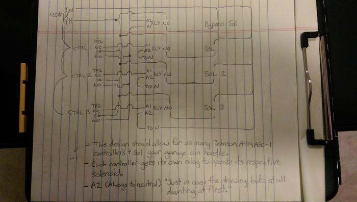
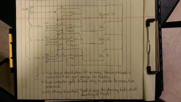
Hey everyone. Jcaudill is right. I haven't been around in a little while. Got back in touch with him to see if he had resolved his problem and he said no. So I spent a little while building this circuit out and am posting it "for you approval." Basically maybe a check for you circuit tracers to make sure I am not leading anyone astray.

For those of you who were involved with this thread originally I guess I kind of went full circle from what the original solution was. The only reason I had done so is because the OP had already bought the equipment so I was just trying to help him save a buck or two.

The inclusion of another controller + sol defeats the original design. Hope this helps you out Mr. Caudill and anyone else that would endeavor with something like this. If anyone sees a problem please let me know so I can resolve it. Thanks.

[edit]
Found a mistake already, fixed it on the drawing. Uploaded so IMAG0082 is the most current.

The only thing I don't like about this design is all the relay coils are always actuated (energized) unless the controller changes its state. I couldn't think of a better way though keeping it simple, leaving room for expansion, and leaving the ability to switch off any controller at any time and still have the rest of the system operating correctly.

Johnson419forGlycolCooling.jpg


IMAG0082.jpg
 
Back
Top