• Please visit and share your knowledge at our sister communities:
  • If you have not, please join our official Homebrewing Facebook Group!

    Homebrewing Facebook Group

Need electronics/electrial help -

Homebrew Talk

Help Support Homebrew Talk:

This site may earn a commission from merchant affiliate links, including eBay, Amazon, and others.

jcaudill

Well-Known Member
Joined
Dec 2, 2010
Messages
990
Reaction score
93
Location
VA Beach
Hello - I am by no means an electrical/electronics guru. I do have some basic knowledge - and I have some experience with Arduino as well so I know how to solve my problem using Arduino. But I'm hoping I can solve it without it. Here's what I'm doing:

I have two normally closed 110v solenoids connected to basic 419 temperature controllers. When the temp falls out of range the 419 opens the solenoids. Chilled liquid will flow through these solenoids when open, and past when closed. Past both solenoids I have another 110v solenoid that is normally open. So when both normally closed solenoids are closed, liquid flows past and through the open solenoid.

But when one of the two (or both) of the normally closed solenoids is open, I need the normally open solenoid to close so the max flow is available to the open solenoid(s). Making this work with just one closed solenoid would be a piece of cake. But with two I have no idea if it's possible and how.

Anyone who has expertise in this arena have any idea? Each solenoid has just two wires (no ground) and polarity doesn't matter.

Any help would be appreciated!
 
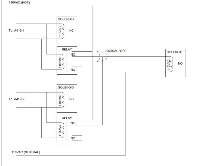
You use a pair of relays w/110vac coils connected in parallel with your normally closed solenoid coils, so when one of the solenoids opens the corresponding relay will close. Then wire the relay switch sets so they both source 110vac on their common legs. Then connect their NO points together and then on to the normally open solenoid coil.

Now when either NC solenoid opens, its relay will close and cause the NO solenoid to close...

Cheers!

I cannot believe I never replied to this to say thanks! Now - turns out I still have the same problem :) I tried to address this mechanically but getting the check valve pressure right has been challenging.

I am not particularly great with electronics. Is there any chance you could draw a rudimentary diagram so I can see this visually? One thing I will tell you that may or may not matter is the polarity on the solenoids is reversible. Hell maybe it makes it easier!

I'd appreciate any help you could give.
 
Try this on for size.

Relays with 110VAC coils aren't rare, I've done a few projects with some over the years, most recently using some beefy units to remote a well pump control circuit...

Cheers!

relay_OR.jpg
 
Much simpler - and cheaper. Something like this, or this, basically a general purpose DPDT switching relay with a 110VAC compatible coil and enough contact rating to handle your solenoid coil (which shouldn't be more than a couple hundred milliamps)...

$T2eC16VHJGwFFY-SmV)bBSMD1-!HZ!~~60_12.JPG


Cheers!
 
Last edited by a moderator:
Great thanks. So I think I understand this diagram but one thing I want to confirm. On the A419 sides, the 110 to the solenoid and to the relay are both from the output of the A419 right? So only when the controller is calling for load does the relay and the solenoid get energized.

Boy I really wish I understood relays better! So looking at these DPDT relays - basically I'm only going to be using 4 of the 8 terminals right?

Thanks again.
 
On the A419 sides, the 110 to the solenoid and to the relay are both from the output of the A419 right? So only when the controller is calling for load does the relay and the solenoid get energized.

Yes, and yes.

Cheers!
 
Ok so I got some relays today and I'm about to make this happen!

This is what I ended up with - it's a 120v DPDT 15a relay.

relay.jpg


I am trying to figure out how to wire this up based on the diagram above. I am going to assume 13 and 14 are the hot and neutral. And since this is a DPDT relay, I will also assume I'm only using one side of it? Now I'm just trying to figure out which terminals are normally open and which are closed. I don't know enough to figure that one out. I'm assuming it's either 11 and 12 or 11 and 14.

Help?! And THANKS!
 
A1 to A2 is your coil. If you look at the diagram you will see 11 and 12 touching. That is normaly closed. 14 is your normaly open contact.
 
Ok so then 12 and 14 would be normally open until energized and then they will close?
 
A relay diagram is almost always shown in its de-energized state. Using the IED ( ) designations, the Normally Open (NO) contacts are 11/14 and 41/44. The Normally Closed (NC) contacts are 11/12 and 41/42.

The 120VAC coil is between A1 and A2. It doesn't matter which is connected to hot or neutral. BTW, you will need two of these relays to match the diagram posted by day trippr.

Ok so then 12 and 14 would be normally open until energized and then they will close?
No.

11 and 14 are normally open and will close when the coil is energized.


Bobbybob, you're mixing the NEMA and IEC references, which both use a 14 on different contacts.
 
13 and 14 are the hot and neutral for the coil to operate the relay.

Point 9 is the common point of one switch between 1 and 5. So 1 is NC and 5 is NO with relation to point 9. So the same goes with the other side, points 4, 8, and 12 with point 12 being the common.

I'm looking at the point numbers on the inner part of the whole diagram. Those points should reference to the base that the relay is attached to.

Hope that helps.

[edit] Ha ha. In the time it took me to write this others had already responded.
 
Also I just looked at the diagram supplied earlier by someone else. I don't think you need another relay, thats why its DPDT. There are two switches.
 
Also I just looked at the diagram supplied earlier by someone else. I don't think you need another relay, thats why its DPDT. There are two switches.

He definitely needs two relays to construct a logical OR circuit here.

They could each be SPST style, but those are likely harder to find than the typical 8-pin DIN style DPDT general purpose relays...

Cheers!
 
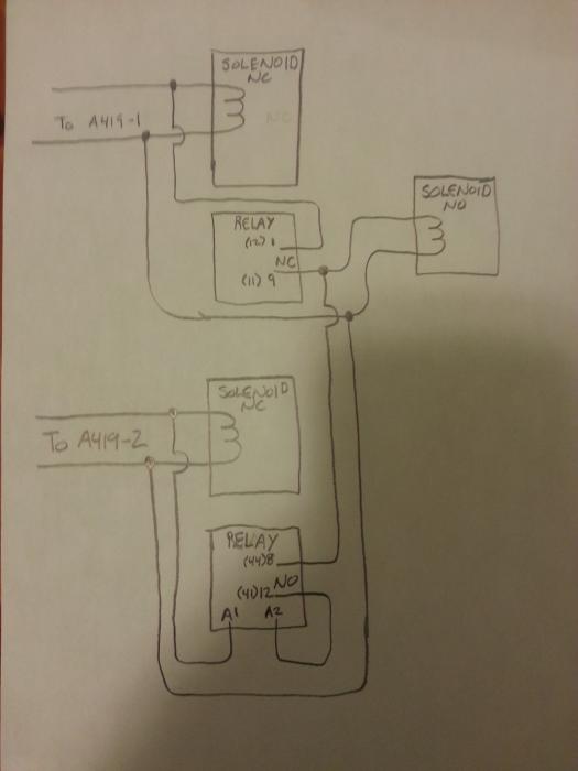
How about this. One relay. Should work. Let me know if I am wrong though.
Sorry for the crudity of my drawing. I can do it faster with pencil and paper though.

dpdt3sol.jpg
 
Close, but I don't think it works.

If A419-1 is not "hot" but A419-2 is, the slaved solenoid will never turn on, as the NO points are still open, hence the relay coil won't energize...
[edit] In fact it appears the relay coil would never energize regardless of which controller is "hot"...

Cheers!
 
Oh. From the original drawing you supplied I thought they were just switches. I pulled up the product sheet and you have an NO/NC and Com to work with. Its a single stage controller so you have only heat mode, or cool mode. I noticed a cut in or cut out for both modes, but its one or the other as far as I can tell.

@The OP. From the sound of the first post, you have two separate controllers? Its just a guess. One controller operates sol 1, one controller operates sol 2, and you want both to operate sol 3? Thats what I'm getting out of it.

Thats why I drew up the circuit the way I did.
 
I agree with day trippr's analysis. The upper section of NC Solenoid and NC Relay should close the NO Solenoid just fine when the controller supplies 120vac. However, I don't see how the relay coil can ever be energized. A catch-22, A2 remains isolated UNTIL the coil is energized but that can't happen because it's isolated.
 
Thats cool. I'm gonna go ahead a bow out of this one. I think its really dependent on whether the OP is using one or two controllers. That and I think this is for fermentation control, or a HERMS setup, but I am not sure.

@the OP. If you are using two controllers and do indeed end up using my little diagram. Then your hot would goto the both the controllers Com, and the neut from the returns from each side (A419-1, and A419-2) would goto the NO terminals.

If you are only using one controller, then you would have the hot wire (to sol 1 and sol 2) going to the com, and the neut legs from each side of the drawing going the NO and NC terminals. I can't figure out for the life of me why you would want a setup like this with only one controller though as your third solenoid would always be on, which is why I am going to bow out unless I get some better information.

Either way. @ Day Trippr. Thanks for supporting this forum and helping the OP. Same goes to everyone else.
 
[...]
@The OP. From the sound of the first post, you have two separate controllers? Its just a guess. One controller operates sol 1, one controller operates sol 2, and you want both to operate sol 3? Thats what I'm getting out of it.

That is the correct set of criteria.

Thats why I drew up the circuit the way I did.

Still wouldn't work...

Cheers!
 
[...]I can't figure out for the life of me why you would want a setup like this with only one controller though as your third solenoid would always be on,

Not true - well, because there are two controllers. If neither A419 is "hot", the slaved solenoid coil is cut off.
Nobody's trying to solve the "single controller" problem here ;)

Either way. @ Day Trippr. Thanks for supporting this forum and helping the OP. Same goes to everyone else.

Cheers! :)
 
As I understand it the OP is designing a chilled liquid, cooling system. The NO solenoid is used as a pressure bypass for the pump. When one or both controllers call for cooling, its associated NC solenoid will open, and the relays are used to close the bypass solenoid.
 
How about this. One relay. Should work. Let me know if I am wrong though.
Sorry for the crudity of my drawing. I can do it faster with pencil and paper though.


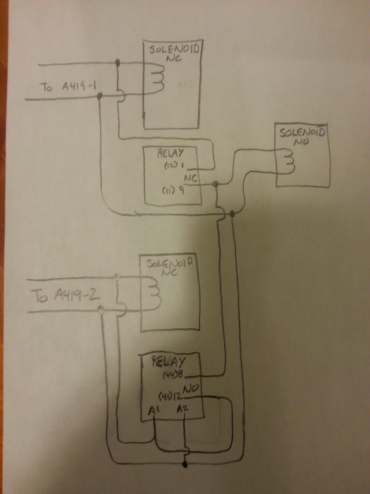
I think this might actually work with 1 small change.

Assuming the top inputs are 120 and bottom neutrals...

Take the A2 input straight down to the neutral, don't loop to NO. Coil needs a neutral.
From the A1 hot input to the coil, loop that around to the NO input you have labeled 41(12)

In the end, it seems you've taken both neutrals to sol-3 (that's fine), and the 120 will be chosen from the NO or NC.

There might still be something wrong with that, I'd have to draw it out and look at it.
 
^Ok, that's a bit of brilliance. Assuming both controllers source from the same branch circuit there really aren't any issues, and the "math" totally works.

Cheers! :mug:
 

Latest posts

Back
Top