Native ESP8266 BrewPi Firmware - WiFi BrewPi, no Arduino needed!

Homebrew Talk - Beer, Wine, Mead, & Cider Brewing Discussion Forum

Help Support Homebrew Talk - Beer, Wine, Mead, & Cider Brewing Discussion Forum:

This site may earn a commission from merchant affiliate links, including eBay, Amazon, and others.
@Bigdaddyale and @Thorrak As an inexperienced solderer I check for lack of continuity on all adjacent solder points. I also check along traces to points where there should be conductivity. But I'll check them again.

I have a variable DC supply and a fixed 5v psu. Could I power the 3.3v and 5 v pins directly and separately when the mini is plugged into a brand new empty rj45 pcb I haven't touched yet? Then I could incrementally solder in components. Then the RJ45 next if the direct 3.3v powers the mini and talks to wifi and lets fermentrack see it.


The components that convert from 5v to 3.3v are on the D1 mini, and are used both when powering via USB as well as when powering via a 5v PSU. The fact that you're not having issues when powering via USB when the chip is disconnected from any other hardware but are having issues when powering via USB when the chip is connected to other hardware means that the issue you're having is with that other hardware.

It's also possible that it's an issue with the D1 mini board that you're using, but given the above set of facts (works with USB but nothing else, doesn't work with USB when plugged into the bare PCB) I'm still thinking that it's a hardware issue with the PCB.


If I suspect my software on my SD should I reflash and start over or is there a command line option for reinstalling Fermentrack?

Given what you're describing I'm of the mindset that your problem is likely not related to the raspberry pi, but to something hardware related. If you delete the Fermentrack folder/user, you could just re-run the installation command and it should effectively reperform the installation.
 
Like Bigdaddyale said - My 2 cents - -

As a no-nothing, about the programming end it, I do start over with a new formatted blank SD card, as this usually works for me. After I somehow destroyed the ability for the scripts to be properly assembled .....
Fermentrack installed soooo easy, without even having to set up your Sensor assignments, or wondering what to flash, other then your significant Other .....
 
FermentcamaraPi - ? Any suggestions on what camera, to give me real-time video of the fermentation bucket/blowoff ? Ideally I do not want it to have to tie into the RaspberryPi, but best to hook remotely into the ESP8266.

Has anyone used the ArduCAM for ESP? Just wondering how to position a camera to "dangle" over my blowoff bucket, so I can see how the fermentation is progressing. Along with a Gravity transmitter, this would keep me from having to go to the brewery after pitching yeast, to see if all is happy....

That might work? I’ve never used ArduCAM so I have no idea what it can provide feature-wise.

One thing of note though - you may already be planning for this, but even if you went the ArduCAM route, you would need two dedicated micro controllers — one for the BrewPi controller firmware, and one for ArduCAM.

I was wondering if I would need a separate ESP8266...Maybe wait until the Thorrak-Eifel-TiltPi is ready and try to get my "Wish List" working.

My Conical's sit outside of my walk-in-cooler,(I'm and HVAC Tech/Master Plumber), so I made one ), so lighting is not a problem day_trippr. I just was not sure if this camera could be integrated into the ESP8266 or WiFi with my RaspberryPi router/monitor to view from my cell phone in the middle of the Night, ...when I'm loosing sleep thinking about, if my Brew is Happy...

]
 
FermentcamaraPi - ? Any suggestions on what camera, to give me real-time video of the fermentation bucket/blowoff ? Ideally I do not want it to have to tie into the RaspberryPi, but best to hook remotely into the ESP8266.

Has anyone used the ArduCAM for ESP? Just wondering how to position a camera to "dangle" over my blowoff bucket, so I can see how the fermentation is progressing. Along with a Gravity transmitter, this would keep me from having to go to the brewery after pitching yeast, to see if all is happy....
This might work. For 8 bucks it's worth a try. https://www.homebrewtalk.com/forum/...no-arduino-needed.586476/page-56#post-8530271
 
Sometimes just putting a "search" into HBT is a no-brainer.....
I just wasn't sure if trying to hack away at this would end up putting a Monkey Wrench into my FPi.....I am a Plumber you know!
What's the harm? Just reformat another card and download the Fermentrack all over again! That's what an armature like me does!
I try it soon and get back to you Know-it-ALLS with my sob story.
Thanks!
 
Finally getting around to updating my original brewpi+arduino setup to use Fermentrack.
My old setup has still been running strong all these years later, even as a pile of wires and crap on top of my fermenter. I've only had 1 relay board(really just 1 relay on that board) go out in the nearly 5 years since i made that thread.

One note that im not sure has been brought up or not, but the script failed originally and after digging through journalctl it turns out it was failing to i nstall nginx-full becacuse my existing brewpi install was running on port 80.

I had to stop my apache 2 service, then the install went through fine. You might want to add this to the install script?

Maybe its just a side effect of my old ass install and setup that no one else has, but thought i'd mention it.
 
Finally getting around to updating my original brewpi+arduino setup to use Fermentrack.
My old setup has still been running strong all these years later, even as a pile of wires and crap on top of my fermenter.

One note that im not sure has been brought up or not, but the script failed originally and after digging through journalctl it turns out it was failing to i nstall nginx-full becacuse my existing brewpi install was running on port 80.

I had to stop my apache 2 service, then the install went through fine. You might want to add this to the install script?

Maybe its just a side effect of my old ass install and setup that no one else has, but thought i'd mention it.

Yeah - there's a warning about it in the script, but it's not exactly the most effective.

That's one of the first things to fix when I next circle back to the install workflow.
 
Finally got it installed but having some problems with the script.

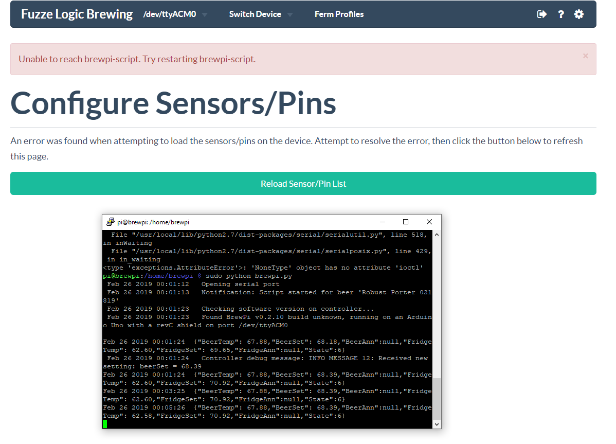
I reflashed it with RevC firmware, and added it as a controller (advanced to ttyacm0), but it never shows the LCD Screen, and when i go to add sensors it says it cant communicate with brewpi-script.

So i went into putty, into my old /home/brewpi/brewpi-script folder and ran python brewpi.py, which immediately crashed out saying it didnt have write access to my current brew.csv file. So i ran sudo python brewpi.py and its now running and showing 0.2.10 firmware and I can see my temps in the console yet i still see nothing in Fermentrack, or when adding sensors.

I went and checked the Process Spawner log and its just spamming this im unsure if its related to me trying to set things up earlier or what.

INFO:processmgr:New BrewPi device found: dev-/dev/ttyacm0
ERROR:processmgr:Could not spawn process: dev-/dev/ttyacm0
INFO:processmgr:New BrewPi device found: dev-/dev/ttyacm0
ERROR:processmgr:Could not spawn process: dev-/dev/ttyacm0
INFO:processmgr:New BrewPi device found: dev-/dev/ttyacm0
ERROR:processmgr:Could not spawn process: dev-/dev/ttyacm0

Any help you could provide would be great. Thanks you can see in the photo below . I tried rebooting my RPI with no luck.

*Edit* I also went into fermentrack's brewpi-script folder and tried launching and it just tells me that there is no module zeroconf? I assume because im not running from the venv? If i run it from the python venv\bin it does nothing then eventually times out and says "Not ImplementedError: only dbconfig installations are supported in this version of brewpi-script". I cant help but wonder if i just need to start over on this RPI if its clashing with my old BrewPi install?

Capture.PNG
 
Last edited:
The two definitely do not get along as we’ve been talking about elsewhere. I just did a clean Fermentrack on late-model Stretch and did not have those issues so I’d recommend flashing the SD card again and giving it a new go.

I have made a little tool for prepping for headless operation if you are interested:

https://www.brewpiremix.com/headless-raspberry-pi/

The page itself is for new folks, but scroll down to where you see “Headless Pi” for a screenshot and download link. I use it a few times a day when I’m in testing mode. That + balenaEtcher and it feels like Raspberry Pi has entered the (very early) 20 century. :)
 
Finally got it installed but having some problems with the script.

I reflashed it with RevC firmware, and added it as a controller (advanced to ttyacm0), but it never shows the LCD Screen, and when i go to add sensors it says it cant communicate with brewpi-script.

So i went into putty, into my old /home/brewpi/brewpi-script folder and ran python brewpi.py, which immediately crashed out saying it didnt have write access to my current brew.csv file. So i ran sudo python brewpi.py and its now running and showing 0.2.10 firmware and I can see my temps in the console yet i still see nothing in Fermentrack, or when adding sensors.

...

*Edit* I also went into fermentrack's brewpi-script folder and tried launching and it just tells me that there is no module zeroconf? I assume because im not running from the venv? If i run it from the python venv\bin it does nothing then eventually times out and says "Not ImplementedError: only dbconfig installations are supported in this version of brewpi-script". I cant help but wonder if i just need to start over on this RPI if its clashing with my old BrewPi install?

To @LBussy 's point, if you're running it on a Pi that already has BrewPi-script installed, you're likely having conflicts over which instance of the script has access to the serial port.

You will need to run from within the venv -- The screenshot you posted is using Python 2.7, but the rewritten brewpi-script that is bundled with Fermentrack is Python 3.4 (3.5?) and up only. The syntax for running it is:

python -u /home/fermentrack/fermentrack/brewpi-script/brewpi.py --dbcfg Kegerator​

...where "Kegerator" would be replaced with the name of your fermenter as set up in Fermentrack.
 
Reinstalled Stretch and Fermentrack and its alive.

I have all the parts to build my iSpindle coming over the next 2-3 weeks so Ill try that out once i get it built. I also have an extra esp8266 coming i may use to replace my arduino. Then again maybe not..the arduino doesnt have as many uses besides brewpi as an esp8266 does.

I bought one of the XL Big Pet containers, but im not sure still which sled i need have my brother in law 3d print still.
http://rover.ebay.com/rover/1/711-5...0001&campid=5338413729&icep_item=132860252241

If anyone here knows that'd be great and save me some time.

None of the drawers in git match up with the dimensions i see for it, but i know its the most common container used...i did some research but never really found an answer.
https://github.com/universam1/iSpindel/tree/master/drawer
 
Last edited:
I have all the parts to build my iSpindle coming over the next 2-3 weeks so Ill try that out once i get it built. I also have an extra esp8266 coming i may use to replace my arduino. Then again maybe not..the arduino doesnt have as many uses besides brewpi as an esp8266 does.

Fuzze, is This what your looking for? Looks like the smallest you can get to house your WortHydro.

I bought a TILT about a year ago for about $130. I am sure your parts list will mayby max out a lot cheaper and you get to build it yourself. The $6.45 for the enclosure blew the budget! I assume its very waterproof???
Getting the Google Sheets to work without stopping multiple times, would make me one happy brewer!
Hope you and Thorrak will post your success build when your done, and you can test it out on us Ginny-pigs....I'll be the first one to screw it up, or plug 110 vac into it and smoke my Wort!
This is a very nice added feature of Fermentrack that I love.
 
Last edited:
@FuzzeWuzze , I always recommend the XXL Petling and this Sled. But since you've already purchased the PETling, perhaps somebody has a recommendation for a sled that works. The XL is about 7mm smaller in diameter @33mm than the XXL @40mm, but the same length according to the descriptions 122mm. All the sleds I'm aware of, including the above are approx. 40mm wide.

@bloombrews , There are a lot of us that are succesfully using the iSpindel. In Fact, I've built 2 for @LBussy and 2 for @Thorrak that I hope work as well as mine do. If you have access to a 3D printer for a decent price and a soldering iron, they can be built for less than $30 each.
What PCB are you using with this sled?
 
Thanks to everyone that has contributed to the this ferment controller project. I have mine running and really happy how it is holding the temps in my SS brew bucket that is in a chest freezer. I am using an Arduino board with a Raspberry Pi 3. The only small issue I have is when my fermentation completed I changed the temp to cold crash and it took 3 days to get to my cold crash temp. It would idle at a higher temp, I would think it should stay cooling until the beer hits the desired temp. I know during fermentation we would want slow temp changes, but with cold crashing I would rather it go straight to that temp since fermentation is done. Are there any settings for this or is it just the nature of the software? Thanks!
 
Thanks to everyone that has contributed to the this ferment controller project. I have mine running and really happy how it is holding the temps in my SS brew bucket that is in a chest freezer. I am using an Arduino board with a Raspberry Pi 3. The only small issue I have is when my fermentation completed I changed the temp to cold crash and it took 3 days to get to my cold crash temp. It would idle at a higher temp, I would think it should stay cooling until the beer hits the desired temp. I know during fermentation we would want slow temp changes, but with cold crashing I would rather it go straight to that temp since fermentation is done. Are there any settings for this or is it just the nature of the software? Thanks!

How exactly did you set it to cold crash? Did you use a profile, use a beer constant, or use a fridge constant?
 
I created a profile initially for the fermentation. Then when I was ready to crash I changed the beer constant to my cold crash temp.
 
fwiw, my ipa and neipa profiles include a two day cold crash to 36°F. Makes it easy...though I still have to remember to hook up the CO2 feed beforehand...

Cheers!
 
Update. I got in more new Mini this time from @Thorrak 's recommend supplier. They look much different. I used Fermentrack to flash one. Am able to connect to it and BrewPi script runs. Debug connection fails a couple of control tests.
 
Last edited:
Did you complete setup (by connecting to the AP that the ESP created and configuring it to connect to WiFi)?

Yes.

Then I needed to hook 3.3v direct to the Mini to get it to energize and hook up to Wifi. When I tried 5 v to the PCB with the Mini on it the 3.3v pin was only 0.1 or less. So I just tried 5v directly to pin on the mini while not on the PCB and I got 3.3 at the 3.3v pin on the mini. Could the BSS138s be the problem?

On a separate issue if I run
pi@brewpi:~ $ sudo find . -type f -exec grep "esp8266" '{}' \; -print

Shouldn't I get something pop up other than this
Binary file ./.config/chromium/Default/Favicons matches
./.config/chromium/Default/Favicons
Binary file ./.config/chromium/Default/History matches
./.config/chromium/Default/History
Binary file ./.cache/chromium/Default/Cache/ec534397d07f9c5f_0 matches
./.cache/chromium/Default/Cache/ec534397d07f9c5f_0
 
Yes.

Then I needed to hook 3.3v direct to the Mini to get it to energize and hook up to Wifi. When I tried 5 v to the PCB with the Mini on it the 3.3v pin was only 0.1 or less. So I just tried 5v directly to pin on the mini while not on the PCB and I got 3.3 at the 3.3v pin on the mini. Could the BSS138s be the problem?

Possibly -- It still sounds like you have a short somewhere, based on what you're saying. It could be the BSS138s given that they do touch both 3.3 and 5v, or it could be somewhere else on the board. The only thing that the BSS138s themselves not working would impact would be the LCD (though if there was a short associated with them then that could explain some of the issues you've encountered!).

As a side note, you shouldn't ever run (or need to run) any of this project on 3.3v alone. Although it (theoretically?) should work with the D1 if it's by itself, the project is set up to run on a combination of 5v (from the power supply) and 3.3v (from the voltage regulator on the D1 mini). For

If you want to test if it's your PCB, try running the D1 mini when it's not plugged into any PCB at all, and is powered via USB. It should still appear as a WiFi AP, be available to set up in Fermentrack, be available/visible in Fermentrack, etc. If it works like that, then plug it into the PCB without anything attached (no power supply, no LCD, no relay, no temp sensors). Then, attach the LCD, then the temp sensors, then the relay, and test at each step to see if it still works. Then disconnect the USB and attach the power supply.

There is also the "build test" firmware available in Fermentrack to flash that will test all the components -- assuming the LCD works, it will use it to display the outcome of each of the hardware tests.

On a separate issue if I run
pi@brewpi:~ $ sudo find . -type f -exec grep "esp8266" '{}' \; -print

Shouldn't I get something pop up other than this

No - none of the files are named "esp8266" in a Fermentrack build.
 
Possibly -- It still sounds like you have a short somewhere, based on what you're saying. It could be the BSS138s given that they do touch both 3.3 and 5v, or it could be somewhere else on the board. The only thing that the BSS138s themselves not working would impact would be the LCD (though if there was a short associated with them then that could explain some of the issues you've encountered!).

I had no intention of using an LCD so since I wasn't going to use one I took one of the pcb's and unsoldered the BSS138s...... no change Mini still doesn't work on the board

If you want to test if it's your PCB, try running the D1 mini when it's not plugged into any PCB at all, and is powered via USB. It should still appear as a WiFi AP, be available to set up in Fermentrack, be available/visible in Fermentrack, etc. If it works like that, then plug it into the PCB without anything attached (no power supply, no LCD, no relay, no temp sensors).

Yes I had tried that. The D1 Mini works on its own when powered by USB or with Wifi on a bare board no resistors or mosfats with power supply Only soldered on screw terminal for 5v. Still getting the failed "controller response test" on debug. Temp sensors not being seen only pin 13, 14 & 16 Heat, cool & door 4.7K resistor wired between vcc and data on probes.
 
Yes I had tried that. The D1 Mini works on its own when powered by USB or with Wifi on a bare board no resistors or mosfats with power supply Only soldered on screw terminal for 5v. Still getting the failed "controller response test" on debug.

Temp sensors not being seen only pin 13, 14 & 16 Heat, cool & door 4.7K resistor wired between vcc and data on probes.

Wait wait wait -- these two statements would actually point at two separate issues. Which of the following two scenarios is occurring:

Scenario 1 - Fermentrack doesn't see your controller at all when you have it plugged into your PCB. The "LCD" display in Fermentrack shows "Script starting up", you can't see pins/sensors on the "Assign pins/sensors" page, and the "Debug Connection" link tells you that you're failing the "controller response" test.

Scenario 2 - Fermentrack does see your controller when you have it plugged into your PCB. The "LCD" display shows a standard BrewPi LCD screen, and you can see pins/sensors on the "Assign pins/sensors" page. If you try to run the "debug connection" test, you may still see it fail the "controller response" test.

If it's scenario 2, that's mostly expected. The "controller response" test is expected to fail if something is already connected to your BrewPi controller, as the controller only supports one connection at a time. (In this case, it's supporting the actual brewpi-script connection rather than the debug script). If it's scenario 2, then I'm guessing your issue is with the temperature sensor wiring. Post photos of your board/D1 mini, as well as your temperature sensors and I'll see if I notice anything.


If it's Scenario 1, then at which of the following stages did it stop responding in fermentrack and did you start seeing it fail the "controller response test?
  1. Running the bare D1 mini, not hooked up to any PCB at all, powered by USB, after setting it up via the AP
  2. Plugged into the PCB, powered by USB, but with absolutely nothing else plugged into the PCB (Just the D1 mini)
  3. Plugged into the PCB /w the LCD (may not be applicable for you now), but powered by USB
  4. Plugged into the PCB /w the LCD & temp sensors, but powered by USB
  5. Plugged into the PCB /w the LCD, temp sensors, and relay, but powered by USB
  6. Plugged into the PCB /w the LCD, temp sensors, relay, and PSU, and powered by the PSU
Scenario 2.

But I discovered something that may have affected not seeing sensors. I did not know that there could be a wrong type of RJ45. When sensors weren't recognized I was examining jack and what I thought was a brand was a type "Pulse". I've ordered new RJs.
 
Scenario 2.

But I discovered something that may have affected not seeing sensors. I did not know that there could be a wrong type of RJ45. When sensors weren't recognized I was examining jack and what I thought was a brand was a type "Pulse". I've ordered new RJs.

Scenario 2 is the better one. I’ll add an issue to GitHub about the confusion — if Fermentrack is connected to/communicating with the controller, then the connection test should be an automatic pass.

Can you post photos of your sensors/breakout board/however they’re connected? It might be the RJ45 connector (yours is one that has the LEDs, I think) but I think most of the pins you would have soldered onto the board would have the same pinout. Might be wrong though.
 
GoodBad&Ugly.jpg
Scenario 2 is the better one. I’ll add an issue to GitHub about the confusion — if Fermentrack is connected to/communicating with the controller, then the connection test should be an automatic pass.

Can you post photos of your sensors/breakout board/however they’re connected? It might be the RJ45 connector (yours is one that has the LEDs, I think) but I think most of the pins you would have soldered onto the board would have the same pinout. Might be wrong though.

Success!!!! Turns out it was a couple things.

1) the RJ45s on the pcb without probes dropped the 3.3 volt pins to somewhere under 0.4 volt to a point that the D1 Minis didn't have enough power to hooked up to Wifi without USB. Once I pulled the "pulse" RJ45s off the pcbs voila the D1 Minis showed up on WiFi and Fermentrack could see them.

2) the D1 Minis I had wouldn't register the one-wire devices. Once I flashed the D1 Mini's I got from your recommended source they showed up in the device list.

I don't have anything wired up to a panel yet but I'ved included a photo of the two different D1 Minis and the one of the troublesome "Pulse" RJ45s that I pulled off a PCB. The front and back of the bad Minis is on the right.
 
View attachment 615936

Success!!!! Turns out it was a couple things.

1) the RJ45s on the pcb without probes dropped the 3.3 volt pins to somewhere under 0.4 volt to a point that the D1 Minis didn't have enough power to hooked up to Wifi without USB. Once I pulled the "pulse" RJ45s off the pcbs voila the D1 Minis showed up on WiFi and Fermentrack could see them.

2) the D1 Minis I had wouldn't register the one-wire devices. Once I flashed the D1 Mini's I got from your recommended source they showed up in the device list.

I don't have anything wired up to a panel yet but I'ved included a photo of the two different D1 Minis and the one of the troublesome "Pulse" RJ45s that I pulled off a PCB. The front and back of the bad Minis is on the right.
I thought you were having more than your share of troubles than most people that used the standard BOM. Glad you got it all working.
 
Back
Top