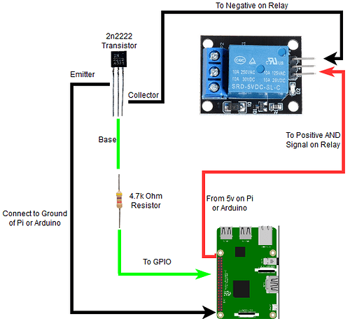
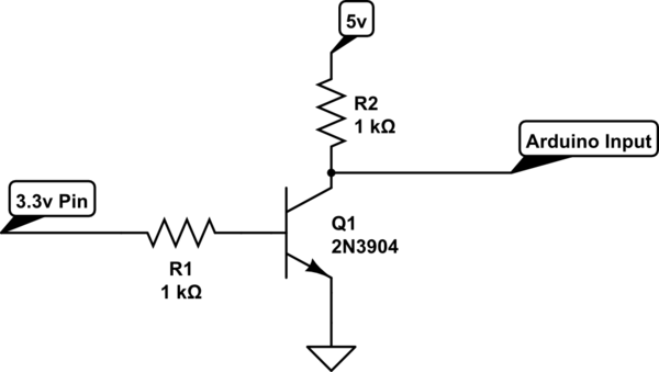
Not sure which PCB design you’re using, but my latest designs break out 5V on a separate pin for this purpose.What would be the best way to step up my 3.3v relay signal to 5v? Could this be integrated into future pcbs?
You are using an out of date browser. It may not display this or other websites correctly.
You should upgrade or use an alternative browser.
You should upgrade or use an alternative browser.
Native ESP8266 BrewPi Firmware - WiFi BrewPi, no Arduino needed!
- Thread starter Thorrak
- Start date

Help Support Homebrew Talk:
This site may earn a commission from merchant affiliate
links, including eBay, Amazon, and others.
I have some of your older boards (1-2 gen). The new boards will shift the cooling signal to 5v?Not sure which PCB design you’re using, but my latest designs break out 5V on a separate pin for this purpose.
Sort of — The signal itself coming off the microcontroller needs to be 3v3, but the relay boards have optoisolators built in to allow the 3v3 signal to switch a 5v signal which then in turn switches the relays.I have some of your older boards (1-2 gen). The new boards will shift the cooling signal to 5v?
The latest PCB design just has a 5V and GND pin broken out to make this a tad bit easier.
This is what @day_trippr ’s schematic was referencing — the JD-VCC pin on the relay board can be hooked up to 5V (with the jumper removed!) and you will be driving the relay with 5V. If you have a convenient way to break out a 5V line to go to the relay board with your current PCB then you don’t need a new design - hook that up and you’re golden.
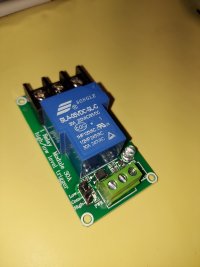
This is the relay I am hopefully going to use. I haven't found a clear schematic yet, but the jumper just says high, com, low, triggers. Don't know if their the same yet.Sort of — The signal itself coming off the microcontroller needs to be 3v3, but the relay boards have optoisolators built in to allow the 3v3 signal to switch a 5v signal which then in turn switches the relays.
The latest PCB design just has a 5V and GND pin broken out to make this a tad bit easier.
This is what @day_trippr ’s schematic was referencing — the JD-VCC pin on the relay board can be hooked up to 5V (with the jumper removed!) and you will be driving the relay with 5V. If you have a convenient way to break out a 5V line to go to the relay board with your current PCB then you don’t need a new design - hook that up and you’re golden.
Attachments
I have no experience with that board, but it looks like it might have an optocoupler wedged in there between the blue relay and the green screw terminal (the chip that has “354” written on the top) so I would guess that the design is able to be triggered with voltage lower than 3v3 (and use higher voltage to then subsequently drive the relay). Not sure how you would hook it up though.This is the relay I am hopefully going to use. I haven't found a clear schematic yet, but the jumper just says high, com, low, triggers. Don't know if their the same yet.
What are the labels for the green screw terminals?
Pos, neg, in1. Does have an optocoupler.I have no experience with that board, but it looks like it might have an optocoupler wedged in there between the blue relay and the green screw terminal (the chip that has “354” written on the top) so I would guess that the design is able to be triggered with voltage lower than 3v3 (and use higher voltage to then subsequently drive the relay). Not sure how you would hook it up though.
What are the labels for the green screw terminals?

$33.99 ($17.00 / Count)
$41.99 ($21.00 / Count)
2 Pack 1 Gallon Large Fermentation Jars with 3 Airlocks and 2 SCREW Lids(100% Airtight Heavy Duty Lid w Silicone) - Wide Mouth Glass Jars w Scale Mark - Pickle Jars for Sauerkraut, Sourdough Starter
Qianfenie Direct

$44.99
$49.95
Craft A Brew - Mead Making Kit – Reusable Make Your Own Mead Kit – Yields 1 Gallon of Mead
Craft a Brew

$53.24
1pc Hose Barb/MFL 1.5" Tri Clamp to Ball Lock Post Liquid Gas Homebrew Kegging Fermentation Parts Brewer Hardware SUS304(Liquid Hose Barb)
Guangshui Weilu You Trading Co., Ltd

$176.97
1pc Commercial Keg Manifold 2" Tri Clamp,Ball Lock Tapping Head,Pressure Gauge/Adjustable PRV for Kegging,Fermentation Control
hanhanbaihuoxiaoshoudian

$7.79 ($7.79 / Count)
Craft A Brew - LalBrew Voss™ - Kveik Ale Yeast - For Craft Lagers - Ingredients for Home Brewing - Beer Making Supplies - (1 Pack)
Craft a Brew

$719.00
$799.00
EdgeStar KC2000TWIN Full Size Dual Tap Kegerator & Draft Beer Dispenser - Black
Amazon.com
![Craft A Brew - Safale S-04 Dry Yeast - Fermentis - English Ale Dry Yeast - For English and American Ales and Hard Apple Ciders - Ingredients for Home Brewing - Beer Making Supplies - [1 Pack]](https://m.media-amazon.com/images/I/41fVGNh6JfL._SL500_.jpg)
$6.95 ($17.38 / Ounce)
$7.47 ($18.68 / Ounce)
Craft A Brew - Safale S-04 Dry Yeast - Fermentis - English Ale Dry Yeast - For English and American Ales and Hard Apple Ciders - Ingredients for Home Brewing - Beer Making Supplies - [1 Pack]
Hobby Homebrew

$58.16
HUIZHUGS Brewing Equipment Keg Ball Lock Faucet 30cm Reinforced Silicone Hose Secondary Fermentation Homebrew Kegging Brewing Equipment
xiangshuizhenzhanglingfengshop

$20.94
$29.99
The Brew Your Own Big Book of Clone Recipes: Featuring 300 Homebrew Recipes from Your Favorite Breweries
Amazon.com

$10.99 ($31.16 / Ounce)
Hornindal Kveik Yeast for Homebrewing - Mead, Cider, Wine, Beer - 10g Packet - Saccharomyces Cerevisiae - Sold by Shadowhive.com
Shadowhive

$53.24
1pc Hose Barb/MFL 1.5" Tri Clamp to Ball Lock Post Liquid Gas Homebrew Kegging Fermentation Parts Brewer Hardware SUS304(Liquid Hose Barb)
yunchengshiyanhuqucuichendianzishangwuyouxiangongsi

$22.00 ($623.23 / Ounce)
AMZLMPKNTW Ball Lock Sample Faucet 30cm Reinforced Silicone Hose Secondary Fermentation Homebrew Kegging joyful
无为中南商贸有限公司
I think I'm mistaken. This design uses the optocoupler in order to allow for both high and low-level triggering (hence the high/low with the jumper) -- not for allowing decoupling of the signal and the power to drive the relay itself.Pos, neg, in1. Does have an optocoupler.
You could still make this work by adding a level shifter somewhere, but it's going to be additional hardware beyond the basic PCB design.
Do you remember on you older pcbs w/shifter do they use all the channels?I think I'm mistaken. This design uses the optocoupler in order to allow for both high and low-level triggering (hence the high/low with the jumper) -- not for allowing decoupling of the signal and the power to drive the relay itself.
You could still make this work by adding a level shifter somewhere, but it's going to be additional hardware beyond the basic PCB design.
No offense intended (maybe I'm not following), but I need my 3.3 i/o to step up to a full 5v for a higher amp relay to switch.
The circuit provides 5V across the relay coils, using an opto-coupled input sufficient to respond to 3.3V signalling levels. By noting the respective voltages I assumed you would follow the rails and arrive at the above conclusion. And if you don't want the optocoupler, drive the resistor at the base of the 2222 with the 3.3V control.
The relay pictured almost certainly uses the circuit I provided, btw. You can see the optocoupler and a 3 pin sot that's surely a transistor of some type. Judging by the trace sizes going through the three pin header, I bet that picks from the NO and NC relay pins and not actually changing the relay behavior...
Cheers!
Last edited:
The design that uses the separate level shifter board?Do you remember on you older pcbs w/shifter do they use all the channels?
Great question -- they do not!

rkhanso
Well-Known Member
- Joined
- Jan 24, 2017
- Messages
- 785
- Reaction score
- 178
wouldn't something simple like this do the job?

or


or

Nope.
I provided the correct circuit above.
Understand completely, or copy faithfully...
Cheers!
I provided the correct circuit above.
Understand completely, or copy faithfully...
Cheers!
Would this be as simple as jumping d5 to the lv side and the hv pin out to the relay? Or is more hardware needed?The design that uses the separate level shifter board?
Great question -- they do not!View attachment 776859
So your saying if I remove the jumper and jump 5v supply to the high pin it should switch properly? With the jumper removed, I already have 5v on the high pin?The circuit provides 5V across the relay coils, using an opto-coupled input sufficient to respond to 3.3V signalling levels. By noting the respective voltages I assumed you would follow the rails and arrive at the above conclusion. And if you don't want the optocoupler, drive the resistor at the base of the 2222 with the 3.3V control.
The relay pictured almost certainly uses the circuit I provided, btw. You can see the optocoupler and a 3 pin sot that's surely a transistor of some type. Judging by the trace sizes going through the three pin header, I bet that picks from the NO and NC relay pins and not actually changing the relay behavior...
Cheers!
This is what I'm saying: the jumper on that relay module may select which relay point to use, which is analogous to inverting the control response without the complexity...

To know for sure would require an ohmmeter...
Cheers!

To know for sure would require an ohmmeter...
Cheers!
Finally attempting my first dry run with Fermentrack, I tried to set up v0.14 serial and had a 66.8 degree offset on the beer temp probe (was reading 3.2 F) that I could not adjust for (wouldn't allow any value).
I also tried the v0.14 Low Delay, but as it is Wi-Fi only and for some reason the communication between the Pi and the Wemos fails every time it tries to update the controller.
I am back to the v0.11 serial and it appears to be working fine.
I am using a Glycol Chiller for my set up and I found that if I have the Chamber temp probe in the glycol(34 F) the SW thinks the "fridge" is too cold so it will not start the cooling cycle (pump in the glycol to the cooling coil in the conical).
I Have the beer temp probe in the thermowell, and the chamber temp probe slipped in between the conical and the neoprene insulating jacket, which the SW liked.
Will see how everything goes over the next couple of days.
This is what I'm saying: the jumper on that relay module may select which relay point to use, which is analogous to inverting the control response without the complexity...
View attachment 776929
To know for sure would require an ohmmeter...
Cheers!
I actually think that this is the schematic for that relay board:

The jumper doesn't seem to select which relay point to use -- both are broken out -- it actually inverts the signal going to the relay.
The P3 header clearly allows selecting between using the NC or NO points.
Haven't figured out the other headers can change "polarity" vs the gpio input...
Cheers!
Haven't figured out the other headers can change "polarity" vs the gpio input...
Cheers!
It appears Thorrak has the correct diagram for this relay. Dc+ directly feeds low jumper and dc- feeds the high jumper pin, the com pin also goes through a 1k resistor to the optoThe P3 header clearly allows selecting between using the NC or NO points.
Haven't figured out the other headers can change "polarity" vs the gpio input...
Cheers!
Last edited:
This seems pretty solid so far. Relay switches on and off promptly.The design that uses the separate level shifter board?
Great question -- they do not!View attachment 776859
Attachments
Glad to hear it!This seems pretty solid so far. Relay switches on and off promptly.
Lalo_uy
Well-Known Member
That diagram is wrong. The colector of the opto is Not conected.I actually think that this is the schematic for that relay board:
View attachment 776988
The jumper doesn't seem to select which relay point to use -- both are broken out -- it actually inverts the signal going to the relay.
And the relay coil is only connected to heather pin3
Hey all, I'm hoping someone can point out what is probably an obvious error I'm making in my ESP8266 Brewpi build. I can't get Fermentrack to recognize any of my DS18B20 probes when mocked up on thorrak's latest "main" and "sensor breakout" PCBs.
It works fine when I just put the 8266 (and even an ESP32-S2 mini) on a breadboard and wire the sensors directly to the ESP using the same power supply. The only measurable difference I can see is that I get ~4.6V at the probe Data pin when wired to the breadboard and only 3.3V when wired to the PCBs (the jumper on the main board is using 5v to power the probes, confirmed with a multimeter).
I'm using a LoLin D1 Mini supplied by thorrak (and a Hiletgo ESP32-S2 mini from Amazon, just to see), probes and power supply from a working Arduino BrewPi build. Im using the docker version of Fermentrack and tried v0.11 and v0.14 firmware on the boards.
Long-time lurker, and very grateful for all the work you guys do!


Is your Ethernet cable straight through or crossover?Hey all, I'm hoping someone can point out what is probably an obvious error I'm making in my ESP8266 Brewpi build. I can't get Fermentrack to recognize any of my DS18B20 probes when mocked up on thorrak's latest "main" and "sensor breakout" PCBs.
It works fine when I just put the 8266 (and even an ESP32-S2 mini) on a breadboard and wire the sensors directly to the ESP using the same power supply. The only measurable difference I can see is that I get ~4.6V at the probe Data pin when wired to the breadboard and only 3.3V when wired to the PCBs (the jumper on the main board is using 5v to power the probes, confirmed with a multimeter).
I'm using a LoLin D1 Mini supplied by thorrak (and a Hiletgo ESP32-S2 mini from Amazon, just to see), probes and power supply from a working Arduino BrewPi build. Im using the docker version of Fermentrack and tried v0.11 and v0.14 firmware on the boards.
Long-time lurker, and very grateful for all the work you guys do!
View attachment 781695View attachment 781692View attachment 781693View attachment 781694
To tell, take a look at the end of the cable and compare the colors of the wires. Should be the same colors in the same order on both ends.
It's a straight-through patch cable right out of the package. Also tried a different cable...same result. I checked continuity between the sensor board pins and the proper ESP pins. Also, there's no continuity on pins that shouldn't have it, so I'm reasonably confident it's not a botched solder job.Is your Ethernet cable straight through or crossover?
To tell, take a look at the end of the cable and compare the colors of the wires. Should be the same colors in the same order on both ends.
Do you have the jumper on the main board selecting the 5v or 3.3v setting? I seem to remember it not finding the sensors if nothing is selected.Hey all, I'm hoping someone can point out what is probably an obvious error I'm making in my ESP8266 Brewpi build. I can't get Fermentrack to recognize any of my DS18B20 probes when mocked up on thorrak's latest "main" and "sensor breakout" PCBs.
It works fine when I just put the 8266 (and even an ESP32-S2 mini) on a breadboard and wire the sensors directly to the ESP using the same power supply. The only measurable difference I can see is that I get ~4.6V at the probe Data pin when wired to the breadboard and only 3.3V when wired to the PCBs (the jumper on the main board is using 5v to power the probes, confirmed with a multimeter).
I'm using a LoLin D1 Mini supplied by thorrak (and a Hiletgo ESP32-S2 mini from Amazon, just to see), probes and power supply from a working Arduino BrewPi build. Im using the docker version of Fermentrack and tried v0.11 and v0.14 firmware on the boards.
Long-time lurker, and very grateful for all the work you guys do!
View attachment 781695View attachment 781692View attachment 781693View attachment 781694

I see you have the jumper on the main board sorry. I gave up of the surface mounted boards due to my limited skills and eyesight but it seems like a similar issue I had with no jumper in place.
I could be off and just guessing but are you meant to have resistors in this area?? It looks like an area for one of the small resistors to be soldered?

Last edited:
What happens if you switch the jumper to 3.3v?It's a straight-through patch cable right out of the package. Also tried a different cable...same result. I checked continuity between the sensor board pins and the proper ESP pins. Also, there's no continuity on pins that shouldn't have it, so I'm reasonably confident it's not a botched solder job.
Pull-ups should be 2k2 for 3v3 and 4k7 for 5v0.
Do you have the jumper on the main board selecting the 5v or 3.3v setting? I seem to remember it not finding the sensors if nothing is selected.
View attachment 781708
I see you have the jumper on the main board sorry. I gave up of the surface mounted boards due to my limited skills and eyesight but it seems like a similar issue I had with no jumper in place.
I could be off and just guessing but are you meant to have resistors in this area?? It looks like an area for one of the small resistors to be soldered?
View attachment 781710
That's an optional solder bridge location if you want to permanently choose a voltage. I'd guess that 90% of builds won't use it, but it was free to add.
The whole reason the selector exists is due to an issue I had with a build once where I had sensors that worked fine with 3v3 but not with 5v. Step one for debugging this symptom is doing exactly what you mentioned and checking to make sure that at least one voltage is selected. Step two is to then check the other voltage.
Step three is to go cry in a corner because these things are almost all knock-offs at this point with minimal quality control...
True, but you can get away with 4k7 for 3v3 with most sensors.Pull-ups should be 2k2 for 3v3 and 4k7 for 5v0.
Similar threads
- Replies
- 10
- Views
- 2K
- Replies
- 3
- Views
- 2K
- Replies
- 7
- Views
- 2K


