Mypin TA4 not triggering heating element

Homebrew Talk - Beer, Wine, Mead, & Cider Brewing Discussion Forum

Help Support Homebrew Talk - Beer, Wine, Mead, & Cider Brewing Discussion Forum:

This site may earn a commission from merchant affiliate links, including eBay, Amazon, and others.

MRMcGovern

Member
Joined
Sep 22, 2012
Messages
15
Reaction score
0
Location
Wallingford
I just finished building my control panel for my RIMS, still need to fix my leaky RIMS tube. When I plug my t-100 probe into my controller, I can see that my set value is 100F, but the outlet for my element never gets powered.

Before I get into troubleshooting the wiring, is there anything I need to do with the controller initially to make it switch the element on via the SSR?

I've changed the scale from C to F, I can see that my alarm 1 light is on, which I'm not using but I believe is set to fire at 90 degrees. My SSR is hooked into pins 3 and 4.

I suppose if there's nothing further I need to do in my settings I'll have to take some photos of my wiring when I'm home from work tonight. Thanks in advance for your help!
when you see the little light next to "out1" turn on you should also hear a click and thats the relay to send power to the ssr.... if that light is on than the pid is doing its job and you have a wiring issue.
 
Thanks for the response augiedoggy. I don't even know what's going on right now... I unplugged my PT-100 and heard the SSR click... But not when I adjust the temperature lower than the current temp, even though the out1 light comes on.

I pulled the cover off of my panel and the light on the SSR lights up when the out1 light turns on. Also the out1 light blinks at a fairly steady rate when the set temp is below the current temp. Any idea what's going on? I'm so confused!

Edit: btw pin 3 on the pid (-) is going to pin 4 on the SSR (-) and pin 4 on the pid (+) is going to pin 3 on the SSR (+)
 
So I tried to attach a photo, I don't have a diagram drawn up. Hopefully you can see how the SSR is hooked up to the PID clear enough. I just took a meter to the output of the SSR and I get like 2mV :( , 22VDC on the input side. Is this a sure sign of a bad SSR?

Edit: I guess it won't let me add a pic from my phone :-/
 
I pulled the cover off of my panel and the light on the SSR lights up when the out1 light turns on.

If the light on the SSR is illuminating with OUT1 then all is ok with your PID. The problem is on the high power, element side.
 
If you SSR is lighting up its not the pid at all.... when the SSR it allows on hot side to make or break continuity and gives power to the missing leg of the element.. I would disconnect you element power to the SSR and check for continuity between screw#1 and #2 when the SSR light is on... by she way you won't here any clocks from the SSR... the paid makes a slight clickl
Basically when the light on the SSR is on so is the element when all is wired correctly and working.

Thanks so much for the responses everyone. This is exactly what I had thought. If the light on the SSR is lit, I should have power across pin 1 and 2 of my SSR. When I put my meter between both of those output pins it only reads 2mV, almost nothing coming off of those pins. So is that indeed a bad SSR? Thanks again!
 
Hey Brumateur, it's the SNR type. This is the exact one I ordered.
http://amzn.com/B0087O6S2A

It doesn't matter at this point since we know its turning on the ssr... when you say you tested it with your meter... how exactly? You should have had the ground grounded elsewhere and you should be seeing 120v at screws #1 and #2 when the light is on and 120v on only one screw when the light is off...
 
Thanks so much for the responses everyone. This is exactly what I had thought. If the light on the SSR is lit, I should have power across pin 1 and 2 of my SSR. When I put my meter between both of those output pins it only reads 2mV, almost nothing coming off of those pins. So is that indeed a bad SSR? Thanks again!

An SSR is a switch, only instead of moving a lever, a small electrical signal switches it on and off.

If it is working i.e. current is being allowed to flow, then there should be no voltage difference across the pins, as you have observed, as both input and output should be at the same potential.

I doubt you SSR is faulty. Your best option is to get some photos or a diagram of your wiring up to check first - it sounds like it could be some trivial issue.
 
Thanks for the response augiedoggy. I don't even know what's going on right now... I unplugged my PT-100 and heard the SSR click... But not when I adjust the temperature lower than the current temp, even though the out1 light comes on.

I pulled the cover off of my panel and the light on the SSR lights up when the out1 light turns on. Also the out1 light blinks at a fairly steady rate when the set temp is below the current temp. Any idea what's going on? I'm so confused!

Edit: btw pin 3 on the pid (-) is going to pin 4 on the SSR (-) and pin 4 on the pid (+) is going to pin 3 on the SSR (+)

You shouldn't hear the SSR or SSR output on the PID click, it's not a mechanical relay. You may hear the alarm output relays click on and off as you pass the alarm points, as will happen if you remove the temperature sensor.

The Out1 light on the PID is blinking because it's controlling the power to the element to be below full power. If the SSR is lighting with it, then it's working correctly. When you adjust the set point, the PID algorithm will take a while to catch up with the change - the integral and differential terms are slowing the response below that of a simple switch or proportional control. It will only apply full power if there is a very large difference between the setpoint and measured temperature for a long time.

If you've used the right connector (and 120V), plug a table lamp in place of your element output and see what it does. A bulb is fast enough to respond to the PID cycle time, so you should see the PWM controlling the average power.
 
Thank you guys so much for the information! It was the stupidest mistake... I had the SSR hooked up totally wrong... It was basically inline between the PID and outlet. I didn't even have 120 going to it. DOH!!! It's working fine now!

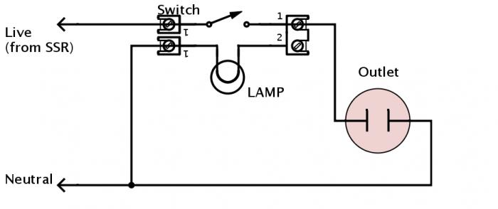
All that is left to do now is figure out how to wire a 3 way switch with an indicator light to switch on the element outlet, and turn on the indicator light at the same time. Right now it does one or the other.
I didnt want to say it but thats kinda what I thought... thats why I made my last statement the way I did...
 
If the indicator uses the same voltage as you are controlling with the switch (i.e. controlling 110v w/ switch and indicator is 110v) then add a wire connecting the output of the switch to the indicator and the other side of the indicator to Ground.
 
If the indicator uses the same voltage as you are controlling with the switch (i.e. controlling 110v w/ switch and indicator is 110v) then add a wire connecting the output of the switch to the indicator and the other side of the indicator to Ground.

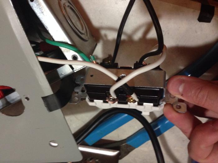
Hmmm... There's only screws for A1, B1, and common. So I have hot coming into A1, and on the opposite side I have common going to my switch, and also a jumper going across to B1. The Common side is only one screw, which is also bridged to the indicator opposite of B1. I'm going to try to post a pic of it. Hopefully what I said makes sense.

What that does now is lights the indicator when the switch is in the off position and the SSR is closed (providing power to the switch), but not to the outlet. When I flip the switch on, the outlet gets power but the indicator does not. I want the reverse of that, where of the switch is on, and the SSR closes, the indicator lights and the outlet gets power.

image.jpg
 
That's good enough for me! When the switch is on and the SSR is closed the outlet is powered and the pilot light is on. When the relay is open and the switch is off, the pilot is on... I'd rather it not be, but I can totally live with it because I can see that my switch is in the off position. The light is also slightly dimmer in this state. Thank you so much for your help! I'm going to call this half of my RIMS project complete!
 
Back
Top