My mostly automated brucontrol setup

Homebrew Talk - Beer, Wine, Mead, & Cider Brewing Discussion Forum

Help Support Homebrew Talk - Beer, Wine, Mead, & Cider Brewing Discussion Forum:

This site may earn a commission from merchant affiliate links, including eBay, Amazon, and others.

Die_Beerery

Well-Known Member
Joined
Aug 21, 2017
Messages
842
Reaction score
641
Thought I would chronicle my build here. Using brucontrol and upgrading from brewtroller/pi/Arduino.

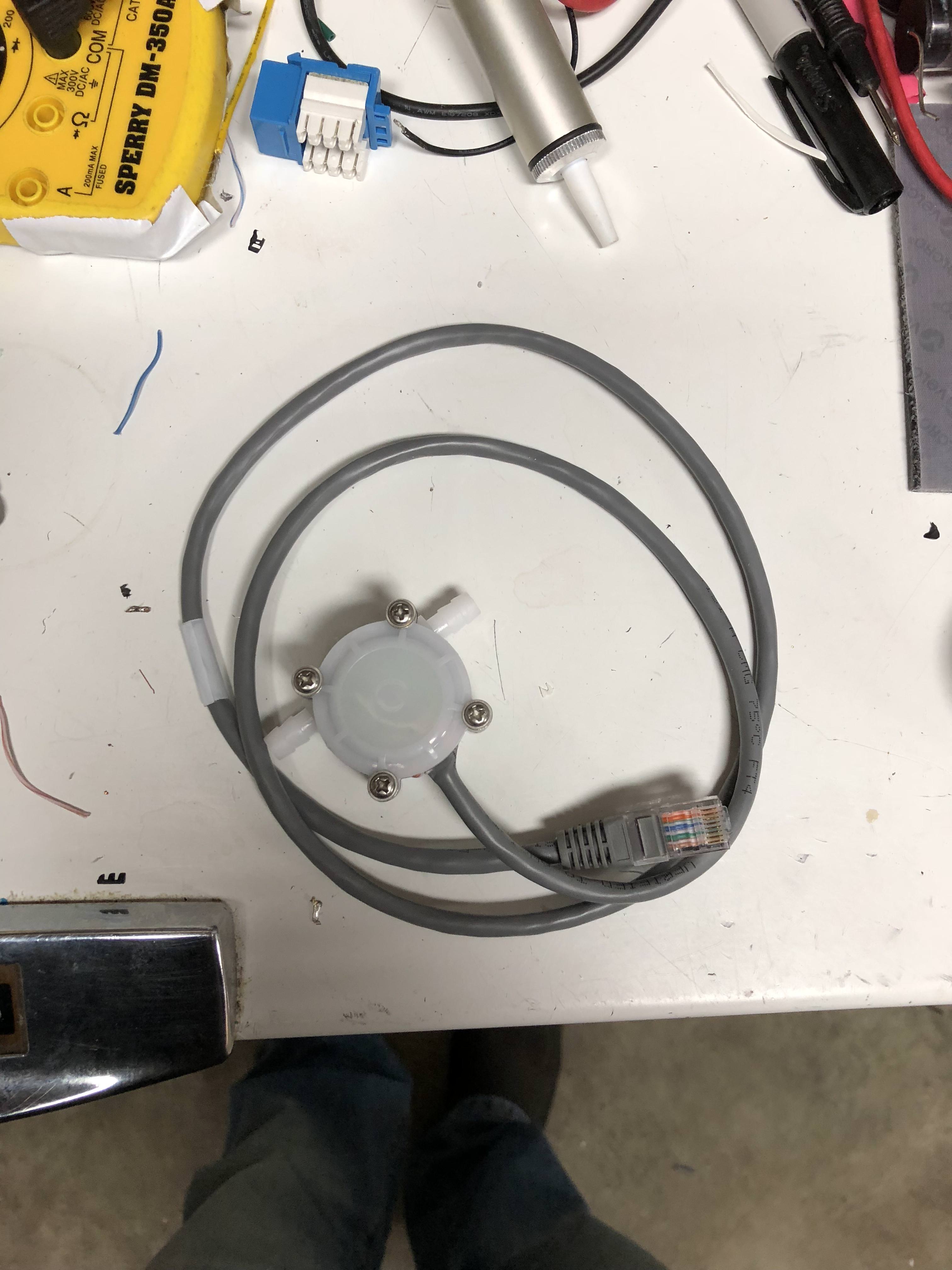
It will be a 3 vessel setup, flow, level, proportional valves,pH, DO, purging and vacuum, fermentation and serving.

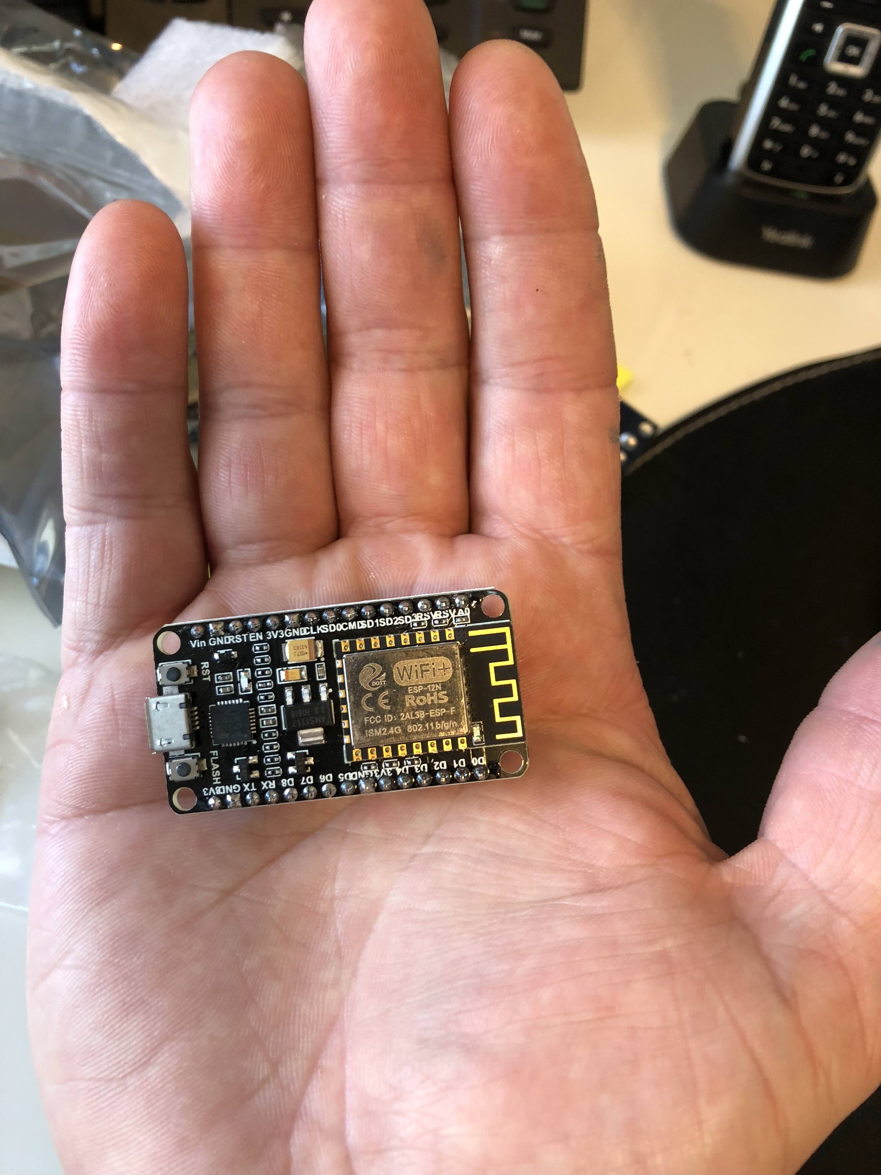
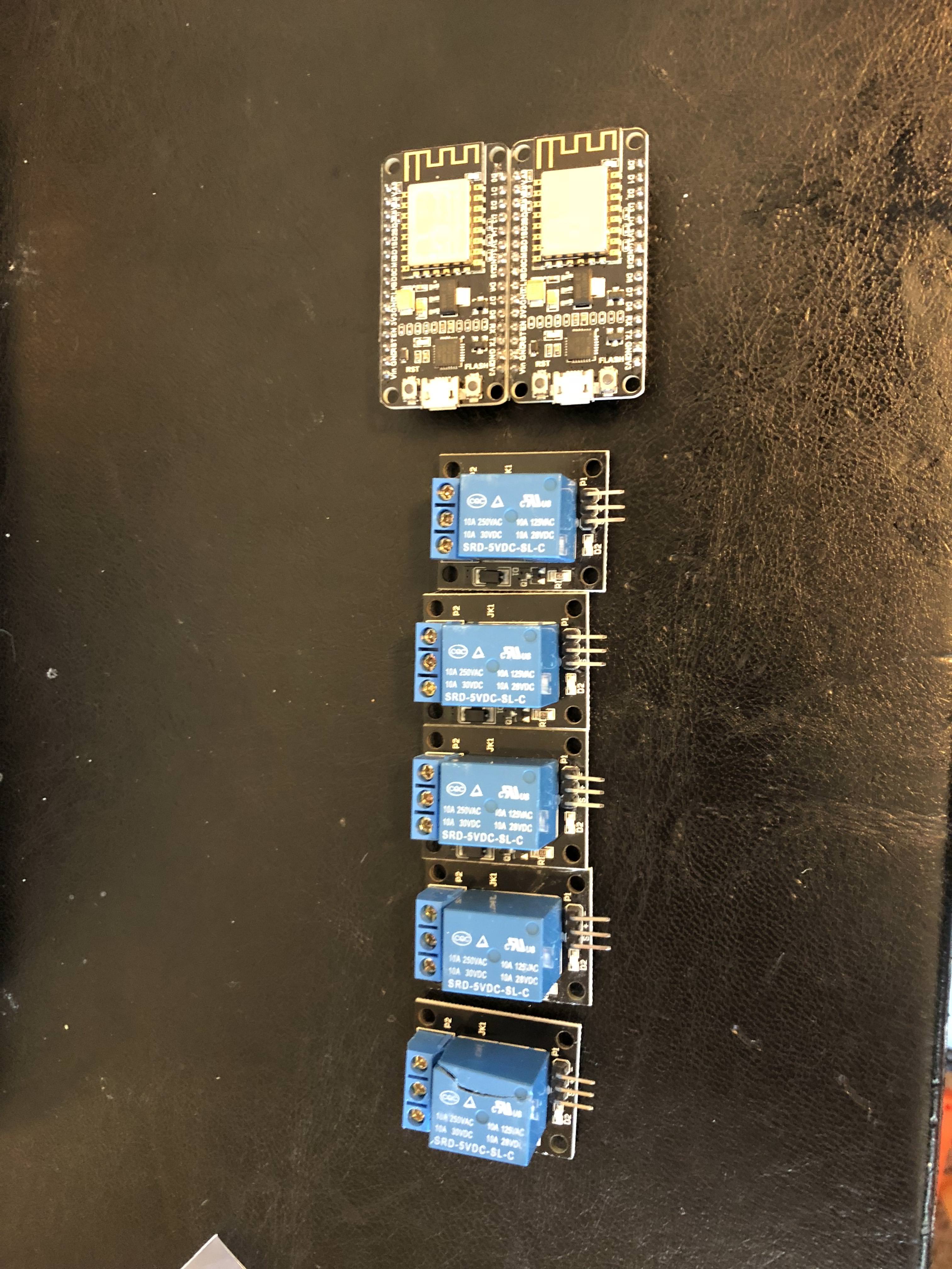
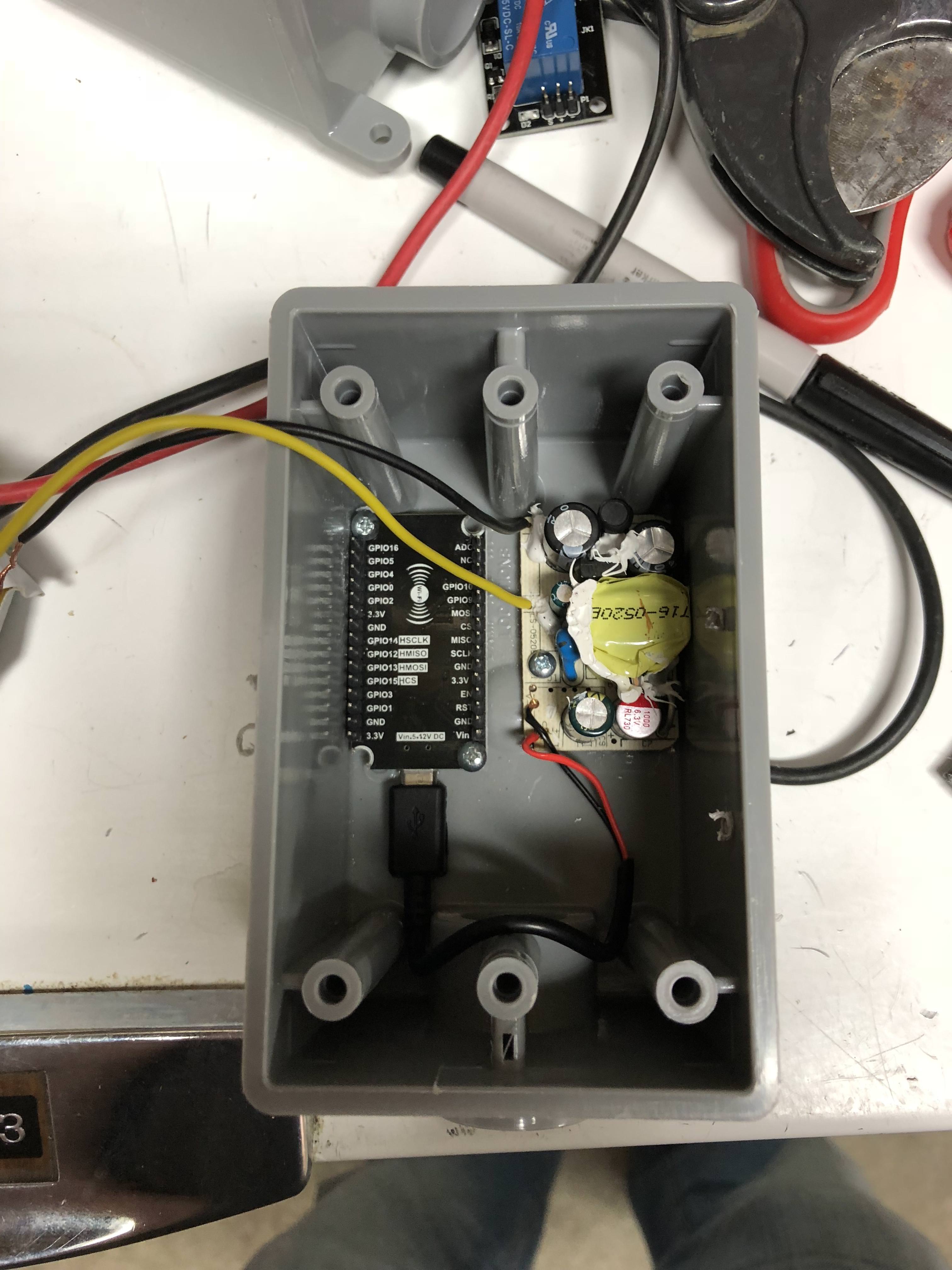
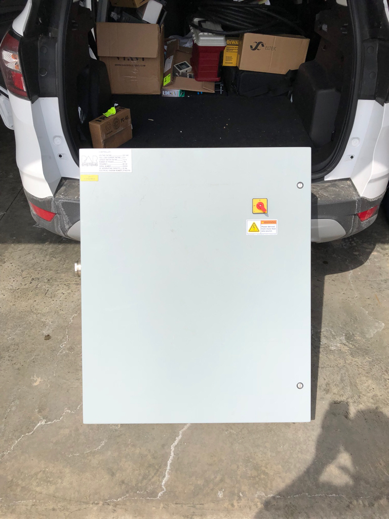
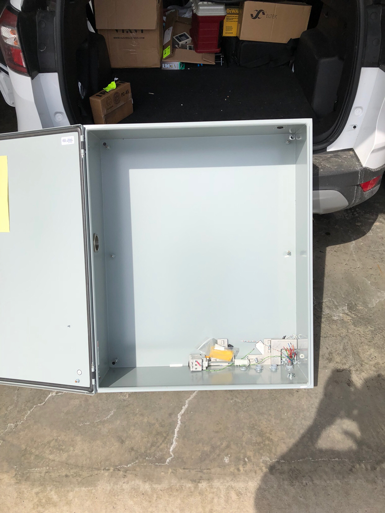
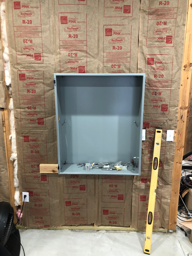
I am in the process of building a brew control. I will be slowly piecing this together, right now I have exactly $35 inevsted into this stuff, and that is for my brewery control. Being as I was already using brewtroller and arduino (brewpi's), I literally have all the parts I need to re-do my controller setup.
I will be adding functionality that I didn't previously have, namely pH, DO, purging and vacuum routines, and integrating a tilt to interface and email me when it's time to spund.


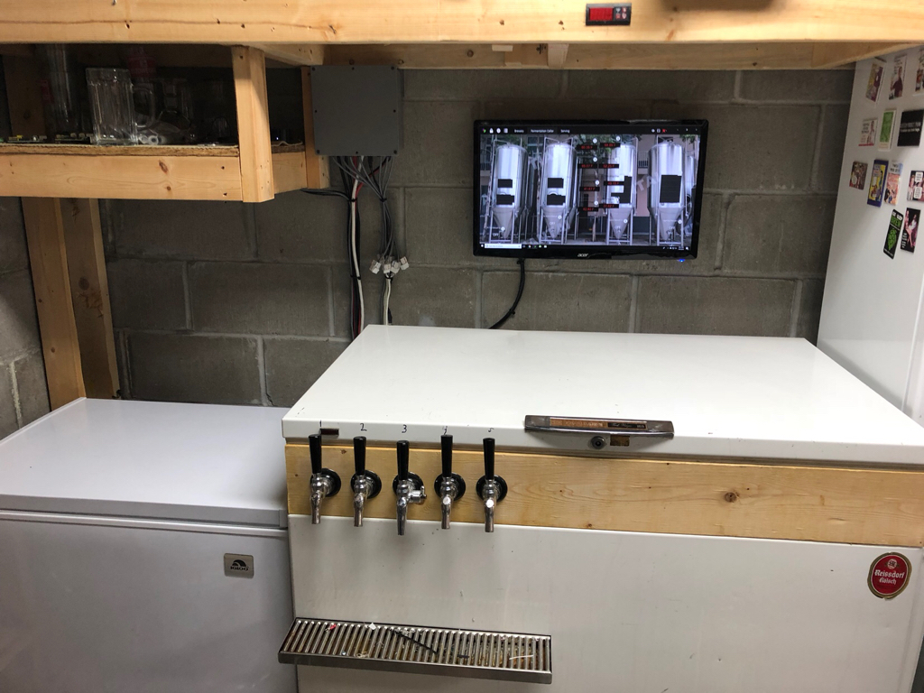
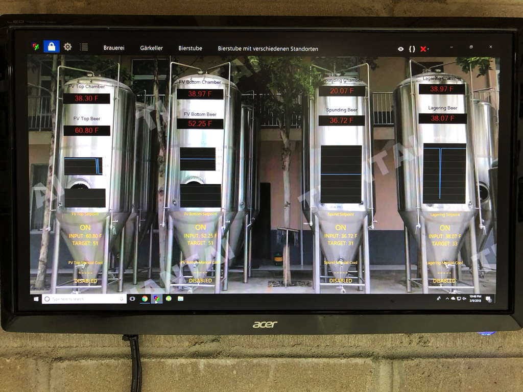
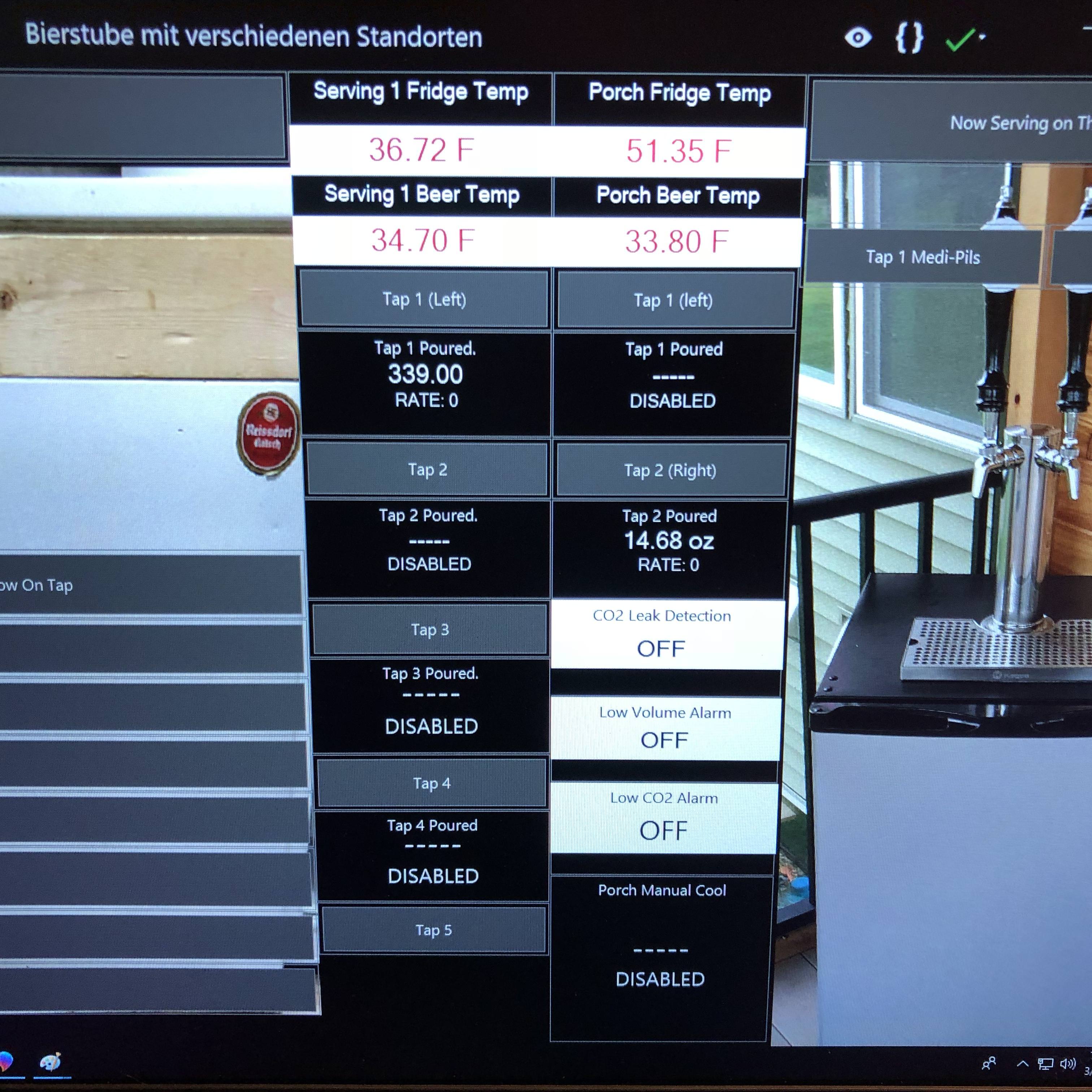
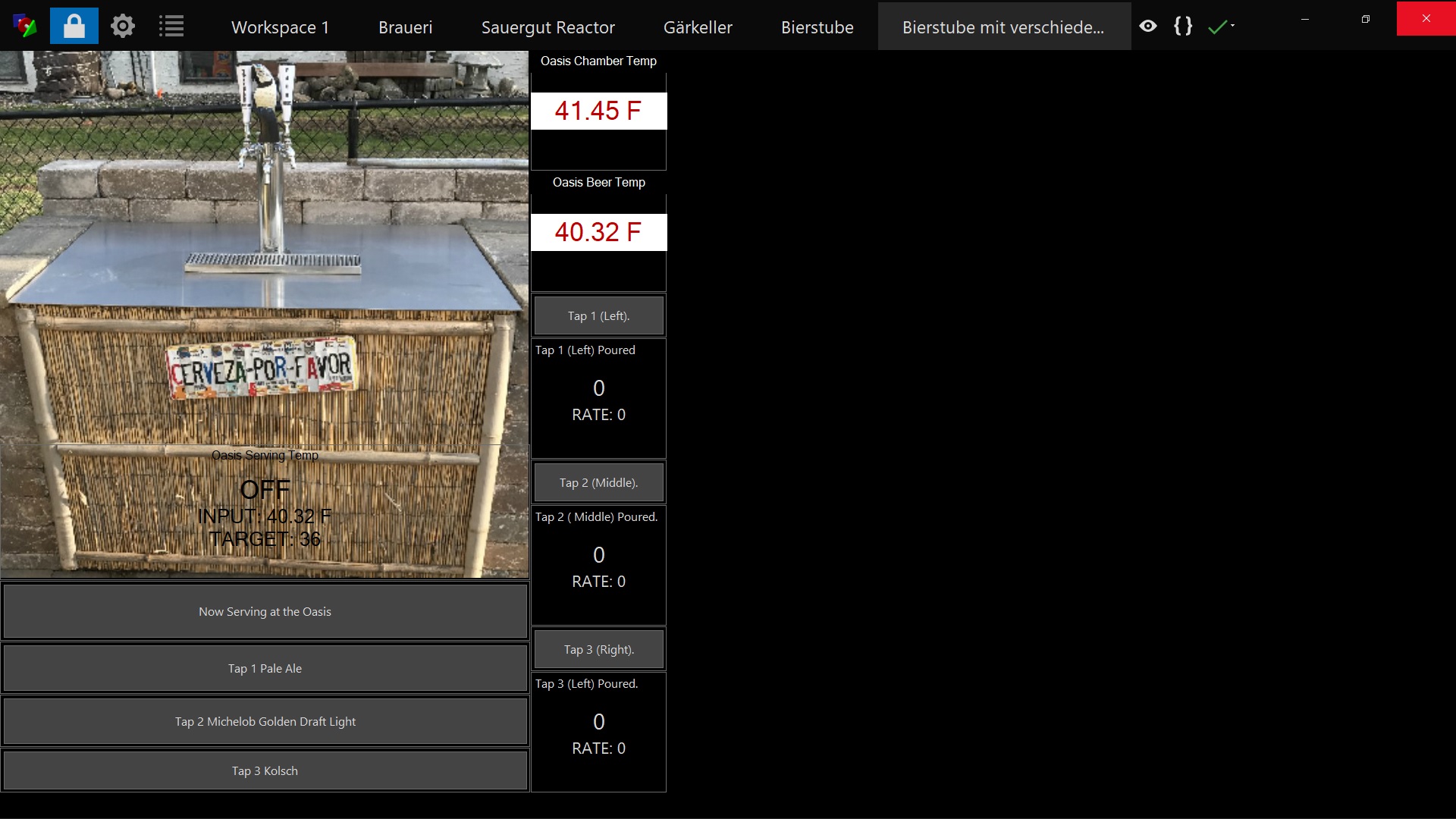
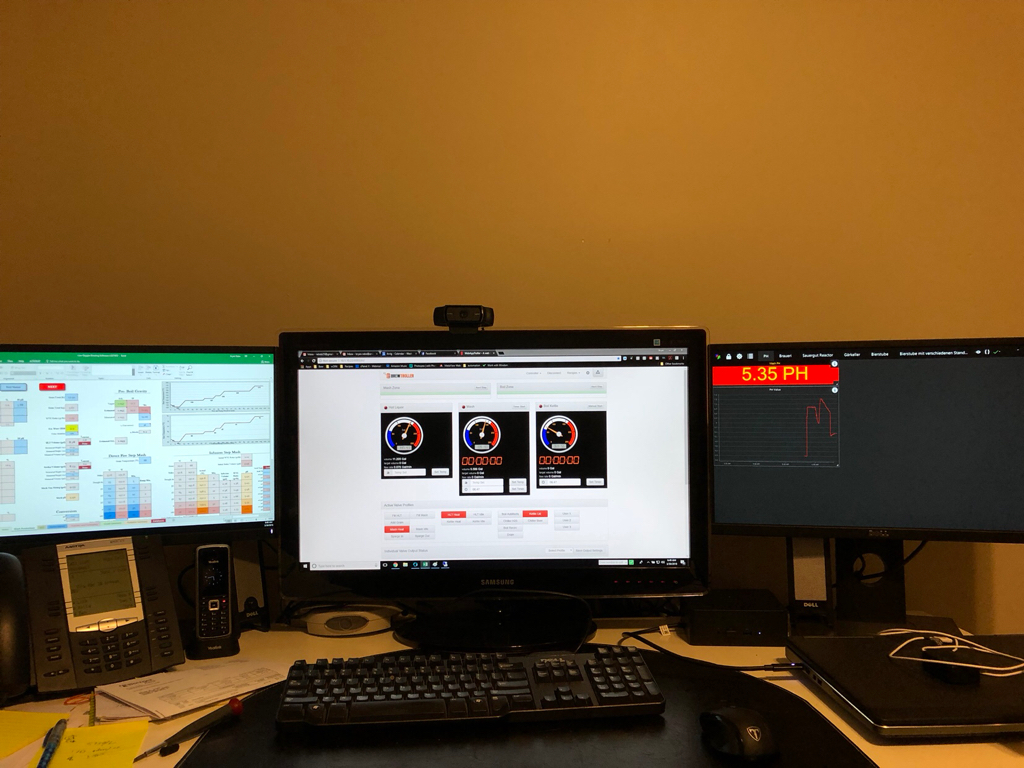
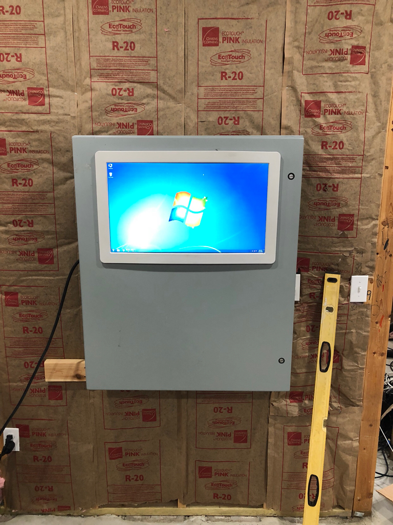
So far all I have got done is some of the fermentation side. 3 out of the 4 vessels. This stuff is probably the coolest most user friendly full automation interface I have seen. It makes me as giddy as a school girl.


IMG_0443.jpg


IMG_0444.jpg


That’s what I got done today.

Most of all thanks to @BrunDog for all the help!
 
Last edited:
Played around with the serving side a little bit today.

I want to use temp sensors, flow sensors, load cell for the CO2, and a meter for o2/co for a leak alarm. Once a poured level is reached ( say 2 gallons left) It will email me the alarm and I can get on brewing the next batch.
 

Attachments

  • Untitled.jpg
    Untitled.jpg
    356.3 KB · Views: 693
e CO2, and a meter for o2/co for a leak alarm.
I do check for CO2 leaks in my setup. I don't worry about the CO2 amount left since I have six CO2 tanks on line (I get free CO2).
If I have a leak the pressure drops and my system will warn me. If the pressure drops more than three times in a fixed time frame the CO2 is shot off to prevent emptying the tanks.
 

Attachments

  • NoCO2-2.jpg
    NoCO2-2.jpg
    321.4 KB · Views: 707
@Die_Beerery how do you plan to plumb in your DO and PH probes? I ask because the DO probe especially has a very low operating temp (120F IIRC) and the ph is only 200F.

I have been building a new entirely sanitary sealed brew system for ~3.5 years now, and I am close to the end. Fortunately, my original build plans suited themselves well to lodo brewing; however, when Brundog mentioned the ability for ph (and now DO) integration with the atlas scientific, my wheels are turning again.

I'd love to implement them, but do not know how to handle for plumbing sake.

Any of your thoughts are appreciated.

-Kevin
 
Hey @cyberbackpacker I am going to be using industrial analog components, that are made for the rigors of brewing. Broadley James components.


I am debating if they will be a per vessel ( 3, so $$$) or right off my mass flow meter, and I could get awa with 1 of each.
Cheers
 
Last edited:
Good to know @Die_Beerery I am quite familiar with AB components-- I have an entire BCS-462 panel stuffed with AB components. Definitely robust and high quality, but with a price to match.

Do you have a link or model number that you are looking at for the DO?

After looking at the Atlas Scientific PH, it does work up to 100C so that is definitely a possibility.

I hear you on trying to use just one versus having to buy multiple (major $$$ for me).

I appreciate your help and any insight.

:mug:
 
Played around with the serving side a little bit today.

I want to use temp sensors, flow sensors, load cell for the CO2, and a meter for o2/co for a leak alarm. Once a poured level is reached ( say 2 gallons left) It will email me the alarm and I can get on brewing the next batch.
Die_Beerery I had the same idea in addition, I was going to add an NFC reader and solenoid valves in order to do access control and record keeping. Football Sunday is always at my house.
 
@Die_Beerery how do you plan to plumb in your DO and PH probes? I ask because the DO probe especially has a very low operating temp (120F IIRC) and the ph is only 200F.

I have been building a new entirely sanitary sealed brew system for ~3.5 years now, and I am close to the end. Fortunately, my original build plans suited themselves well to lodo brewing; however, when Brundog mentioned the ability for ph (and now DO) integration with the atlas scientific, my wheels are turning again.

I'd love to implement them, but do not know how to handle for plumbing sake.

Any of your thoughts are appreciated.

-Kevin

Good to know @Die_Beerery I am quite familiar with AB components-- I have an entire BCS-462 panel stuffed with AB components. Definitely robust and high quality, but with a price to match.

Do you have a link or model number that you are looking at for the DO?

After looking at the Atlas Scientific PH, it does work up to 100C so that is definitely a possibility.

I hear you on trying to use just one versus having to buy multiple (major $$$ for me).

I appreciate your help and any insight.

:mug:
High Temp might not be necessary, the D.O. of boiling water is very low. If you are careful and only sample D.O. as it flows to your fermenter, or before the boil kettle(if you need that number), you should be fine. Dissolved Oxygen is inversely proportional to Temperature. Hot water ability to hold oxygen is less than cold water. It is one of the reasons we need to aerate our wort.
 
Got all my Garkeller (fermentation cellar) moved over from brewpi today. I am running 1 arduino mega ( $12) to run 2 fermenters, 1 spunding chest freezer, and 1 lagering freezer. Also I am running 5 flow sensors on the serving fridge. Not even coming close to maxing it out either. Added enough room for 8 fridges/fermenters/whatever. I just used stuff I had laying around. In love with this stuff.

8f513085b56694ba1f34cfd8f9506427.jpg


a0e1142c5a502a0d4e1cb9d5cf749856.jpg


d9eb13937289e8ae37f5c9e01029691d.jpg


d1e6cc33d24ab85c130b067734fefada.jpg


0a121dbb8c50528b11b630a4eee20d82.jpg
 
I like your new project.
A few of these will make the project look so much nicer.
 

Attachments

  • Strain reliefs-l225.jpg
    Strain reliefs-l225.jpg
    6.8 KB · Views: 346
Added some Labeling on the Garkeller work space

29025686_1091786887630577_7710260139420286976_o.jpg


Got some ESP8266 boards from amazon, so put them to use in the (local) serving fridges. They run about $6 and have on board wifi. So I am monitoring these via IP. I have 4 more to go in at places I stock beer, so I can verify serving temp, and get an email when taps are low. So the "Bierstube" workspace will be home and the "Bierstube Mit" for remote locations.

28958404_1091786874297245_3758236262494896128_o.jpg


I really LOVE playing with this stuff and thanks to much to @BrunDog for putting up with my useless rambling.
 
Worked and completed my "Remote monitoring Setup's".

1 ESP8266 board- I bought 2 on Amazon for $14 - https://www.amazon.com/gp/product/B01IK9GEQG/?tag=skimlinks_replacement-20
XAmN5ct.jpg


1 5v relay- I bought 4 on amazon for $10 - https://www.amazon.com/gp/product/B078478SZ9/?tag=skimlinks_replacement-20
gjrIxrb.jpg


1 5v power supply - $7 on amazon - https://www.amazon.com/gp/product/B0117O020U/?tag=skimlinks_replacement-20
qtuR5u6.jpg


2 1wire temperature probes - I bought 10 for $20 on amazon - https://www.amazon.com/gp/product/B01IOK40DA/?tag=skimlinks_replacement-20

2 flow sensors - boguth from amazon $10 each - https://www.amazon.com/gp/product/B00QC6LI6Q/?tag=skimlinks_replacement-20

Single gang PVC box and some misc fittings bought form home depot.

I happen to work in the "IT" field and have this kind of stuff everywhere, so here are the parts for my expansion modules.

Take a cat5 snip off the end and we are going to un-twist and retwist some wires.
I broke it apart as:
white/orange, 1 wire sensor 5v power
orange, flow sensor 5v power
white/green, 1 wire sensor ground
green, flow sensor ground
white/blue, 1 wire sensor signal
blue, optional flow sensor signal
white/brown, flow sensor signal
brown, flow sensor signal
Therefore 1 cat5 connection will support up to 10 1 wire sensors, and 3 flow sensors.
So I split and re-arranged the whites and the solids.
UrXzy0i.jpg


thEkBKp.jpg


mYrvb5E.jpg


oqte3ui.jpg


FdkuTcN.jpg


nBQ3WwW.jpg


BzTbUPQ.jpg


ONMRXBF.jpg


Completed expansion module that will reside in the kegerator
gM5TyMG.jpg
 
Last edited by a moderator:
Now time to turn to the control box and hardware.

Step 1 was to poke and pry and breakdown the power supply. Got it down to the board, unsoldered the stock wires and re-soldered some new power wires.
F3WHV3X.jpg


hRebAEx.jpg


Soldered together the 5v out from the power supply to:
1 5v output to relay
1 5v output to flow sensor power (orange wire)
1 5v ouput to 1 wire temp sensor power (white/orange and a 4.7k resistor, which will tie to 1 wire signal)
1 5v output to power board

Started fitment in the box
UUAjqTC.jpg


Final internals placement and mounting
[https://i.imgur.com/T2m1FU0.jpg/img]

All internal wiring completed
GPIO 5, 1Wire temperature network
GPIO 0, flow sensor signal
GPIO 2, flow sesnor signal
GPIO 10, Fridge relay trigger
Cat5 with punch down wired in with above color code.

[img]https://i.imgur.com/kTqFLTL.jpg

All Complete
0LJObTj.jpg


Turned my attention to the temperature probes, and flow sensor. First Temp sensor. All I did was attach a cat5 male end to the probe wires, making sure the pinout matched from above.
white/orange, power
white/green, ground
white/blue, signal
kOBx3NU.jpg


For the flow sensor, I dissected it, and unsoldered the original leads, and resoldered in a cat5 cable clipped on one end.
GY5WJYU.jpg


HbX6uH6.jpg


I Then hopped everything up to verify working and started calibrated the sensor, using a gram scale. Once I was satisfied I brought it upstairs and hooked it up.

Itching I poured my first beer from it (Porch, Tap 2 Poured)
zUFlcIL.jpg


Eye balling my .5l mas, I think it was pretty close!
B0bMbgg.jpg


I will be tweaking my interface to make reading in the gui easier, but thats the jist of that part of the new build.

Added poor shakey video
 
You kind Sir is a GENIUS! Using the Cat cables is amazing, and a great time saver.
 
He's a bit of a mad scientist, so I'm betting lots of new stuff!

I am looking forward to him showing us how he is going to leverage networking to be able to monitor the kegerator at his parent's house! I think it will be the first example of BruControl <-> Interface communication across the internet.

One comment I want to offer for those considering something similar... I love the NodeMCU (ESP8266 based) and think they are a steal at only a few dollars each, powered like above will work as long as the power doesn't drop. If the power drops, they will power up, causing a reset. When BruControl automatically reconnects, they will continue as before, however the flowmeter count will be lost (this can be remedied with a script on BC to keep a running count). But, certain boards like the Adafruit Feathers (including the ESP8266 based Huzzah) support LiPo charging & support on-board. This allows you to plug in a LiPo battery, such that if the power drops, the board will remain powered for a while (hours at least). My personal dispenser/fermenter controller has one - and with frequent power flashes in South FL (lightning, dontcha know), it keeps things running should the power fail and the host computer power down if its UPS wears out.

So, consider using a LiPo supporting module or some other backup support for remote modules!
 
Last edited:
He's a bit of a mad scientist, so I'm betting lots of new stuff!


Hey I resemble that statement!

Got some new stuff to play with today.


IMG_0595.jpg


Took a feather

IMG_0621.jpg


Made a mini jumper

IMG_0625.jpg


Used some industrial velcro, and another hacked power supply

IMG_0626.jpg


And @BrunDog and I made this happen.

IMG_0619.jpg


IMG_0618.jpg


IMG_0629.jpg


Wireless Industrial pH meter!
Baby steps!
 
Last edited:
F**k yeah! Well done! No more need for a BT hack! Any chance of a quick sketch of a schematic for the jumper and pinouts?
 
The jumper is just power and gnd, with a resistor across them, since the feather is 3.3v, I used a ~160ohm setup. If using 5v (mega) you will need 250ohms. I then jumpered 3.3v and aref.
SO:

PH transmitter output

+ ----------------->Feather pin A0
| 160ohm resistor
- ------------------>Feather pin GND
 
Nice where did you get yours. I think the one I have is too small.
 
Back
Top