• Please visit and share your knowledge at our sister communities:
  • If you have not, please join our official Homebrewing Facebook Group!

    Homebrewing Facebook Group

Motorizing a MaltMill - Guidance needed

Homebrew Talk

Help Support Homebrew Talk:

This site may earn a commission from merchant affiliate links, including eBay, Amazon, and others.
It might help as well to see what v-belt sizes are available. I think they come in every 2 inches. Then you can set that belt size and see what the center to center distance will be. Makes planning the cabinet easier.

I like the adjustable belt tension on the hinge, but is there a way to really secure it at that tension? Maybe use a long bolt, and a nut on either end of the motor mount as well as the upper side of the cabinet base so you can really secure it at that tension moving and tightening both nuts on the two sides of the motor mount. Seems to me unless the belt is really tight, it will still bounce around a bit.
 
Sweeeeeet. Thanks you guys. For some reason I started thinking you wanted the RPM under 200, and got all nervous.

Good suggestion on how to size the belt, PC, much appreciated. Since I know "about" what size I need, I can pick that up, and as you mentioned, mark the final bolt holes correctly to account for the free play in the belt.

Regarding the adjustable tension, the way I'm looking at the photo, the belt will pull the assembly UP, the nut and washer snug the assembly DOWN, the result is that you put the belt under load, then tighten the nut until the two forces balance out. 's that right?
I suppose if the belt is really skipping/bouncing badly, the tensioner isn't going to compensate enough. But if it bounces that badly would it not likely suggest that the belt is improperly sized?

I'll post up some more pics later this week as we actually start building the enclosure.
I'm excited!! At one point, I was positive I'd never see this project come together.
Once I get this done, I can start pulling apart and leak-troubleshooting my multi-pressure regulator assembly! (Speaking of never ending projects!)
 
Here's what I did. My motor mounts have quite a bit of play, as they are about 2" long. So I'm securing the bolts while adjusting the tension. The belt has about 1cm of play when I push on it. Pretty tight. If it stretches I'll just slide the motor down a bit. Got a good deal on the 14" pulley, as you can see from the wobble. :(


Now I just need to get that Xmas mill installed. I'm getting the Cereal Killer, I'll let you know how it works. :mug:
 
Last edited by a moderator:
Very Interesting!!! You're doing pulley driven but still using a Lovejoy coupler to interface between the pulley and the grain mill, instead of mounting the pulley directly on the mill! I hadn't thought of that option.

Here's the broken bit of bushing sleeve that I was talking about earlier...

ZtxZp.jpg


When it's on the pulley, it looks like it should be that way! But when I remove it, it looks really nasty and jagged.

As long as the sleeve stays inside the pulley, when it's removed from the mill for hand-crank operation, then we should be all good.

I'm working on sketching up the cabinet right now, I picked up some studs and some hardboard at the lumber store the other day, and with any luck maybe I can build a cube like object tonight after work??

Edit: SketchUp Drawing completed!
x0QZ3.jpg
 
Here is where I'm at so far!

4QZJ8.jpg


Still need to sand down the hole where the milled grain passes thru, and then I need to cut the belt/pulley opening larger and mount the motor onto its' hinged platform, and mount the hinges onto the main surface. And do wiring. And test.
 
This is the label off of my exact motor, by the way:
LgdrW.jpg

Hilariously enough, I have NO IDEA why it appears to be upside down. The jpg file itself was right-side-up before I uploaded it.


Now. Time for Wiring.


I have part of it figured out, I think, maybe, at least a little bit. But I would really like a second opinion before I mistakenly burn my house down or anything.

Here is a picture of the contacts on the motor as well as the simple light switch I plan to control it with:
eFQJV.jpg


So on the far end, there is a 120V plug, the wires coming out are standard black, white, green.

Then the wire runs to the switch.
First; which wire gets switched? The black one?

Second; my switch has a green grounding screw on it. Should I ground the cord from the wall onto this? or should I not?

The wire continues past the switch box and on towards the motor. Once we reach the motor, per the appliance guy's instruction; the black wire will be connected to the #4 post (Blue appliance wire).

Likewise the white wire will be connected to the #5 post (Yellow or white appliance wire).

But I do not see any threaded holes or any screws where I could mount the green grounding wire to the motor.
(Whether I grounded the wire to the switch in the first place or not.)
Third, what do I do about this?
Where does the ground go? Do I need to drill a hole and hope I can thread a screw into it?
Do I connect up to the #3 post (Black appliance wire)? No? Never ever do that? Or risk great sadness?

Fourth question. Is it okay to go directly from
Code:
motor -> switch -> exterior cord -> Wall outlet
since this is a freestanding 'appliance'? Or do I really need to go
Code:
motor -> cord -> 120v outlet in a box -> wired to light switch -> exterior cord -> wall outlet
?

Fifth question. Moving on to the advanced course here. IS the motor of a type that can be run in both directions? How would I know that?
If yes -- and IF I wanted to make this reversible by using a three-way switch, how would I wire that?

Muchas Gracias in advance for your advice. :drunk:


Extra information in case it is helpful: Found on a random DIY forum from someone who appears to be familiar with these motors:
The little box is a thermal over load. The end of it that does not got to the coil is one line (usually hot), on terminal 4 (just a terminal). Ordinarily, the start button connects Neutral to the common (terminal 5) of the centrifugal switch, sending power to the run winding and through the NC switch terminal, to the start winding. When the motor achieves operating speed, the cenrtifugal lets the switch out, causing the switch to go from NC to NO (terminal 6), which gets neutral directly. You can, instead, connect neutral to T5.

Terminal 1 and 2 on the switch are to control power to the heater.

the other switch on the frame is likely a belt breakage switch. The belt tensioner would depress thatopening power to the motor in the even the belt were to break.
 
Things are coming together. More info in a minute. But first, my pressing matter at hand: The motor turns the wrong direction. How do I fix it? I tried reversing my black and white wire to which post they go to, but that did not do anything.

What do I do to try to switch rotational direction?? Or do I have to go back to the drawing board? How do I tell if this motor can't be reversed???

There is a loud click during start up and shut off, by the way -- it is a centrifugal start motor -- with no external capacitor. I'm not sure if that's important info.

Here are pictures -- first, of the wiring specifically, then after that my general progress on assembling this. :fro:


Additional pics:


Click to view full size.
 
Looking at the picture in post #35, reversing the motor may be as simple as reversing the motor. Since the drive shaft extends out both ends of the motor, spin that puppy around, move the small pulley/sheave to that end and your off to the races.
 
Yeah, without a capacitor, from what I've read I haven't seen a way to reverse the drive. Mine's the same way. I say flip it around too. It's been a while since I took electrical engineering, so of course I may be off base.
 
My aversion to rotating the motor is twofold:
One, I already cut the wires to-length and it will rotate the electrical connectors to the opposite corner, further out of reach.
And two, the motor does not have a flat on its' drive shaft on the other end.

A local brew buddy also suggested flipping my Maltmill upside down.
I haven't unbolted it to try it yet, but I'm thinkin' about it.
It's a two-roller, and it is not gear driven... it just might work. The bolt holes should be same thread, same spacing. I need to check whether it has the horizontal hole for the hopper screw.

Otherwise, you guys are probably right, fastest fix is to rotate the motor, and grind down the shaft to add a flat.
 
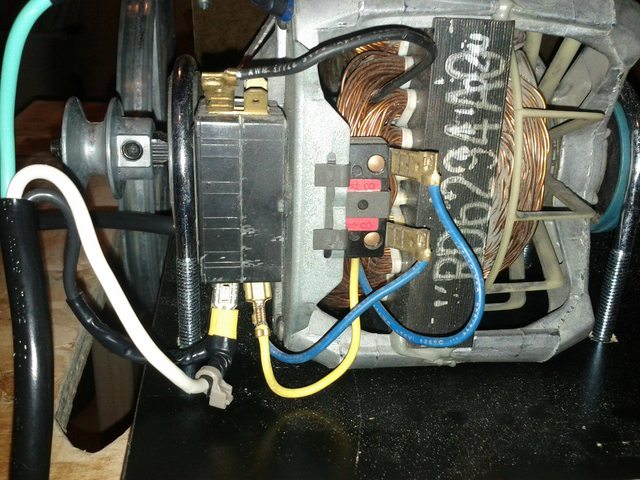
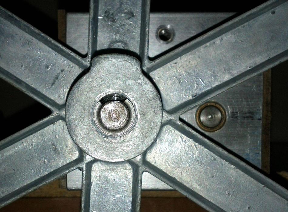
Used Dremel to create a flat on the motor's opposite driveshaft to correct rotation problem. Sheave was loose. Picked up 1/2" to 3/8" shim to correct diameter. Shim was too narrow to fit onto the shaft.
CW-rotation driveshaft turns out to be a different size than the CCW-rotation shaft was. Spent hours using Dremel to reduce driveshaft diameter by hand.
Got motor to successfully rotate mill. Then, put a stress crack into the 2'x2' plywood base due to a weak spot in the deck material, and engine torque. Also encountered belt slippage under load. Devised method to regulate engine belt tension. But, I put further cracks into the motor mount platform during experimentation/testing phase. ARGH.

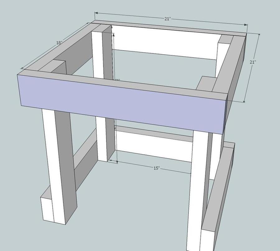
Went to Menards, picked up a 2'x4' of good, 3/4" thick hardboard. Then, I cut a new 2'x2' base, new 8.5"x10" motor mount, new 9"x12" hopper adapter mount. Planned to do the mount now, and the base later.

I traced and drilled the new motor mount. Remounted motor, troubleshot issues. Because I did all of the tracing freehand using the motor mount that had initially been designed for reversed orientation, I was off on a few measurements.

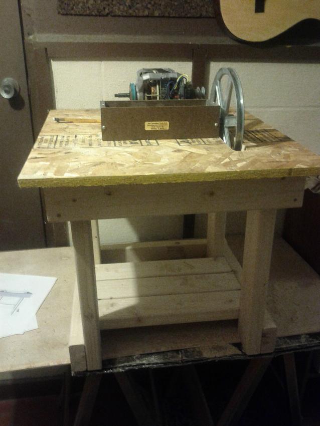
Got mill entirely reassembled and tested it with power again. The pulley alignment is worse than it was on the old mount. :( And the weak spot in the 2'x2' is bad enough that the top deck is flexing up and down as the motor chugs along. It's too weak to put off fixing until later. So, the mill is stripped all the way back apart and has the top torn off of it. I'm re-tracing the new top deck and hope to have it finished tomorrow maybe. At least it'll look quite pretty once it's done.

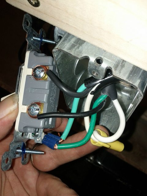
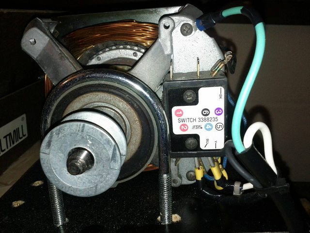
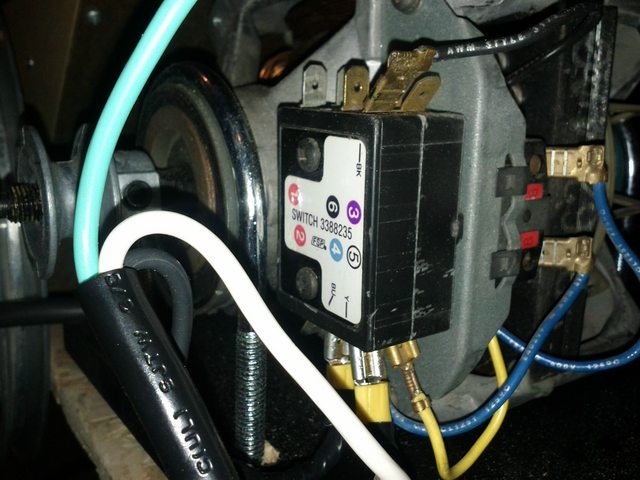
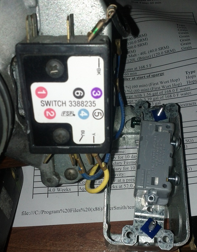
But at this point, the motor/mount assembly, including tension regulation bolt, should all be 100% done-zo. And likewise, wiring is already solid. Just got to measure, cut, drill the top deck, Dremel out the barrel hinge grooves, sand down the grain chute opening, and then it should be operational!

After that, all that remains is double-checking my template on the hopper adapter, drilling cutting and sanding, followed by cutting the Large Hopper (plastic trash can), joining and sealing, and testing!

Once those are done, all that remains is putting together the pulley safety cover, both top-side and bottom-side.

And also cutting dust containment panels (1/4" hardboard) for the four sides, sanding down the front corner of the 2x4" to make easier bucket ingress and egress, and caulking all the seams.

YAY!
 
Pictures post!!!!

Old top deck, with new motor mount, work in progress.


Test fitting...


New Top Deck measured, cut, and assembled!!!!!!!


More shots of the almost-finished mill:


Remaining:

Pick up correct size belt for newly-redesigned motor mount
Cut side panels
Caulk
Sand grain chute edges
Finish safety guard for pulleys
and...
BREW BEER!!!
 
Chriso said:
Pictures post!!!!

Old top deck, with new motor mount, work in progress.
http://img818.imageshack.us/i/img20111228185637.jpg/

Test fitting...
http://img69.imageshack.us/i/img201112281856572.jpg/

New Top Deck measured, cut, and assembled!!!!!!!

http://img521.imageshack.us/i/img20111229223832.jpg/

http://img339.imageshack.us/i/img20111229223910.jpg/

More shots of the almost-finished mill:

http://img607.imageshack.us/i/img20111229223931.jpg/ http://img249.imageshack.us/i/img20111229224000.jpg/ http://img221.imageshack.us/i/img20111229224011i.jpg/ http://img707.imageshack.us/i/img20111229223944.jpg/

Remaining:

Pick up correct size belt for newly-redesigned motor mount
Cut side panels
Caulk
Sand grain chute edges
Finish safety guard for pulleys
and...
BREW BEER!!!

Looks good. And alot of work.
 
I'm using this as a chance to teach myself to build things. I've never really constructed anything before. I just build computers, nor "real stuff". ;)
I would probably not recommend to others that they use a grain mill as their very first project. Some of the measurement/alignment stuff is further in depth than someone who is still learning to measure & cut can really handle.

My pulley alignment was WAY screwed up on the second motor mount because I did it by hand / eyeballing it.

My third motor mount is measured, using a paper drawing and math, and came out bang frickin' on. :D I couldn't be happier!

Off to a chiropractor appointment, then over to Tractor Supply to swap out my V-Belt and pick up some mesh or something to make the safety guard out of. WOOOOOO!
 
Mill in action....


The whole thing


Closeup inside hopper


A little messy, need to create a chute into the bucket


More messy dust, detail of pulley system


My outdoor shelter from the 25mph wind when I was brewing


Mashing my dry stout, heating sparge water


Mid-way through the boil, after it got *much* colder outside
 
I have the same mill and use and old 1/2 hp Black and Decker reversable electric drill. I start the drill prior to pouring in the grain and am able to do 10 - 15 lbs of malt in less that 5 minutes. I do three lbs at a time (my container size).
 
Brewed again last weekend, and figured out a way to wedge 2x4"s under the bucket while it is beneath the mill. Now, the dust is contained and makes it right into the bucket. 11% Rye Malt in my grain bill, this thing didn't even slow down. Took it like a champ.

Mission accomplished.

Also, I made a finger guard for the pulleys....


:D Hey - It's super simple, was easy to make, and will also serve as both a good template, and temporary replacement for, a permanent one once I figure out what I'm going to build it out of. :fro:
 

Latest posts

Back
Top