OK - here are some more details:
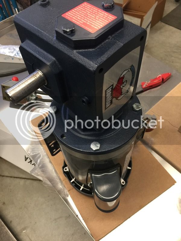
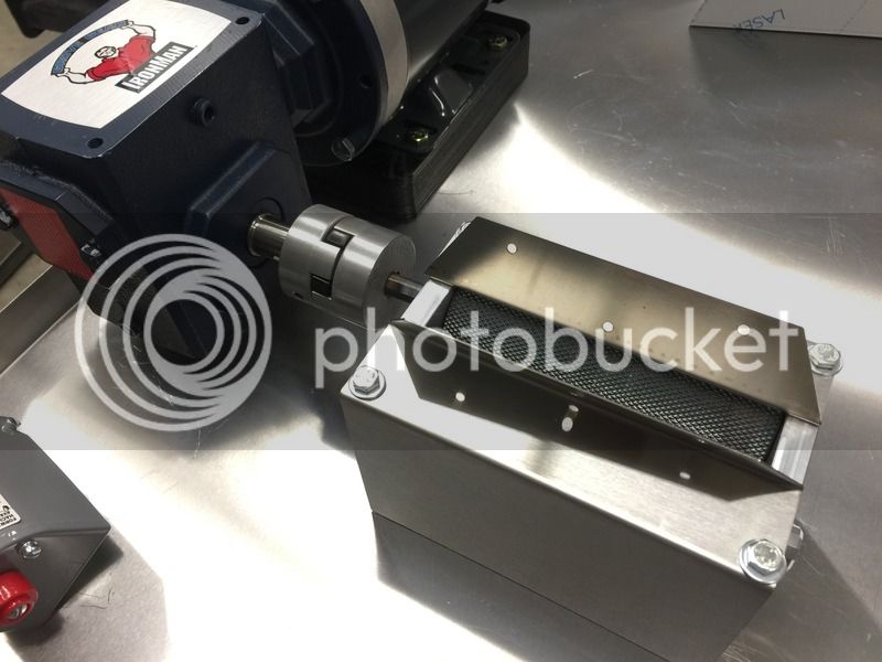
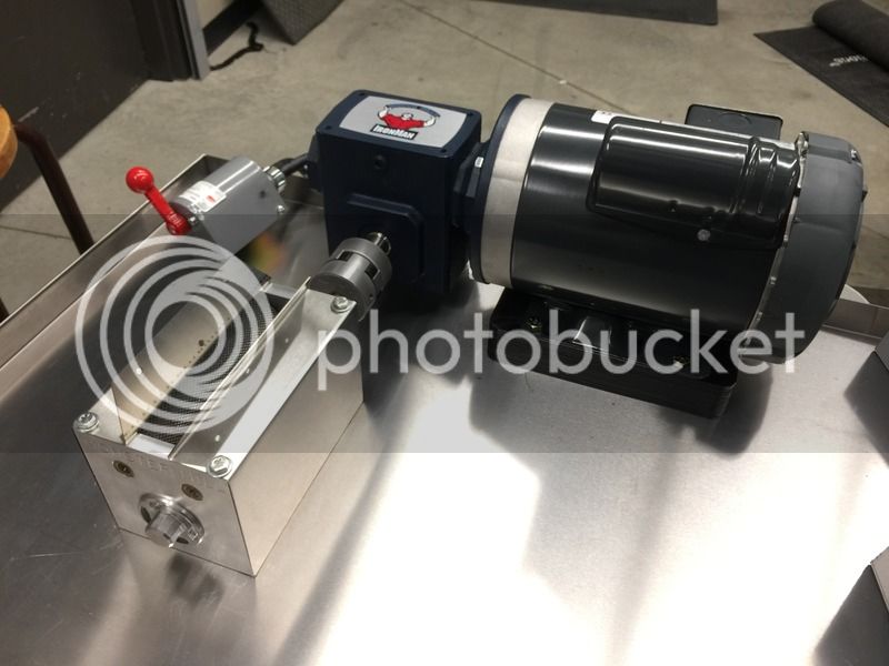
The first pic shows the gear reducer and mill mounting. It turns out that the center of the shaft of the gear reducer is 2.09" from the base. The center of the shaft for a MM-2 is 1.0625" from the bottom edge of the mill. I ended up mounting the gear reducer directly to the my top surface with 4 bolts securing it from the bottom - can be seen in the 3rd and 4th photos. I made (2) 1/2" thick spacers from steel with slightly different hole patterns. The upper spacer has (2) 1/4" holes at the drive end of the mill and (2) 5/16" holes at the other end to allow for a little adjustment. The mill is mounted to the upper spacer with 4 socket head 1/2" bolts. This allows me to mount the mill and adjust it very easily so that the rollers turn freely without too much play. The lower spacer has 4 holes which are big enough to provide recesses into which the socket head bolts securing the mill can fit. Both spacers have 4 matching 1/4" holes for bolts which are threaded into tapped holes on the upper surface. Since the bucket would be sliding directly under the mill, it was important that I design this so that there are no protrusions directly under the mill. Once I powder coated everything, the spacers worked perfectly and the I have great shaft alignment between the mill and gear reducer.
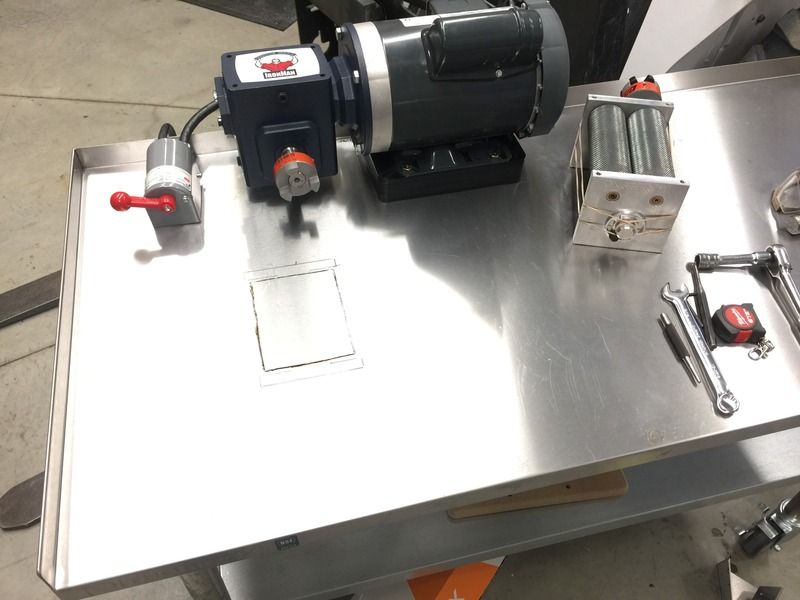
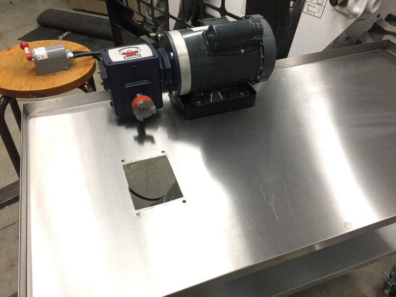
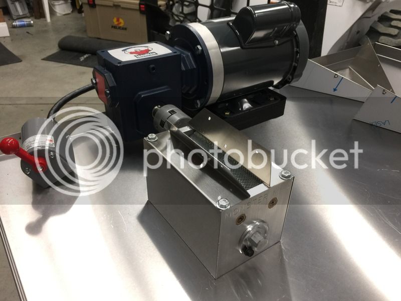
The 3rd picture shows the electrical boxes. The left box is attached to the underside of the top surface with a 1/2" conduit nut attached to the blue plastic conduit next to the motor on the top side. There is also a very short 1/4" carriage bolt under the motor which also secures the left electrical box as well as provides a convenient grounding point. The box contains the start cap - the 2 black lines are zip ties preventing the cap from moving around. 5 wires head up to the motor from this box - ground, the 2 cap lines and switched L1 and N. The right most box is a junction box for the power input and provides a clean way to mount the box on the top surface. The lower box and upper box are connected with a 1/2" conduit nipple and a 1/4" bolt which passes through a hole in the top box, top surface and is threaded into the lower box. This right box offers another grounding point and 4 wires(L1, N, and switched L1 & N) head up to the magnetic switch in the upper box.
The 3rd pic also shows the bucket support. It is a 1/4" piece of steel with a semi-circular cutout designed to support the bucket. I sized it to fit every 5 gallon bucket I could find - I had at least 6 different types in my house. It is supported by (4) carriage bolts. Each carriage bolt has a nut securing the bolt to the top surface and 2 more nuts sandwiching the bucket support at the proper height. If I need to change buckets, I can always adjust these nuts to modify the height of the bucket support. If for some reason I decide that I want to use some odd-ball bucket which doesn't work with my support, I can always cut a new one and as long as it has the same bolt spacing, I should be good to go.
The 4th pic just shows the bucket captured by the support.


![Craft A Brew - Safale S-04 Dry Yeast - Fermentis - English Ale Dry Yeast - For English and American Ales and Hard Apple Ciders - Ingredients for Home Brewing - Beer Making Supplies - [1 Pack]](https://m.media-amazon.com/images/I/41fVGNh6JfL._SL500_.jpg)


