Motor wiring confusion

Homebrew Talk - Beer, Wine, Mead, & Cider Brewing Discussion Forum

Help Support Homebrew Talk - Beer, Wine, Mead, & Cider Brewing Discussion Forum:

This site may earn a commission from merchant affiliate links, including eBay, Amazon, and others.

user 40839

Well-Known Member
Joined
Jul 13, 2009
Messages
1,176
Reaction score
86
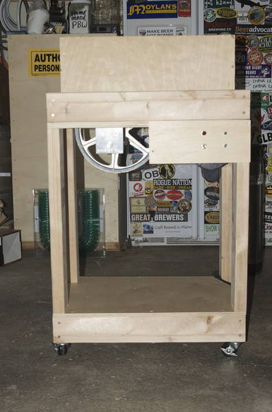
Well, my shiny three roller Monster Mill is here, the capacitor start motor I ordered on ebay showed up, and as soon as my sheaves get here from Drillspot, I plan on finally getting my motorized mill (heavily plaugerized from John Beere's outstanding build) together.

Over the weekend, I was killing time before the World Cup final (woohoo!) so checked out the motor wiring. I was expecting pretty basic stuff, I'd already pored through the other motorizing a mill threads, and based on the motor I tried earlier to use (old garage door opener) as well as the listing page for the motor I currently have, figured the wiring was universal (black, white, blue, red). I was going by the ubiquotous wiring diagram on the lamabrewery page, since I wanted the option to be able to reverse the mill easily, in case of a jam.

The manual says to refer to the motor casing for wiring instructions, which seem simple enough:

dayton_6K490.jpg


Most of the used motors I saw on ebay had wires already coming from the motor - luckily though, I got a brand new one, which did mean I had to wire the thing from scratch. Didn't concern me, at least until I pulled the wee access panel from the back, at which point confusion reigned supreme:

dayton_6K490_guts.jpg


For a start, it SEEMS to me that a some of those terminals (1-5, L1 and L2) are actually the same. For example, 3 and 4 look to be actually the same terminal, just that one's a tab and the other is a screw post (but the tab is attached to the screw post?!?) Same for 1, 2, and L2 - 1 and L2 seem to be just tabs that are attached to the screw post marked 2! Which now confuses me as to where to bring power in - I would have ASSUMED that the black and white wires referred to hot and neutral, but since they seem to be attached to the same screw post, that's surely not the case?

If I don't overthink things (as I usually tend to do), I would say that live (black) from the outlet goes to L1 (where there's currently a purple wire?) and neutral (white) from the outlet would (should?) go to 1, where the white currently is attached. (Or should that be L2?) Adding a switch makes a little less sense to me, I would assume that since the motor specifies interchanging red and black (posts 2 and 4) that I could just string wires from there to a SPDT switch, which would be connected to live (black) from the outlet? But that makes no sense either, since it's specifying that power needs to be provided to L1?

HELP!!

:confused:
 
Looks to me like there should be another diagram on there.
It's kind of a mess and hard to follow. I tried to fine a manual for the Dayotn 6k490 online but it's a bit tough...

From what I can gather, 110AC will go on L1 and Neutral to L2. Terminals 4 and 2 are used to set the direction.
and it can be used one of two ways. Putting 110 on red and neutral on black will set the direction on way, 110 on black and neutral on red will set it the other way.
 
Hmm.. I agree that Black to L1 and White to L2. I think you should physically swap 4 and 2 to get the CW rotation, leaving L1 and L2 alone. If you want to do it with a switch, you should bring those out and have a rotation direction switch on your cabinet. It would really help if we could get an internal wiring diagram.
 
Ground (Green) goes under the green screw, Black - The hot lead of your 110V goes to L-1, White - The Neutral goes to L-2.

115VAC connection for Counter Clockwise Rotation...As Shown in the diagram, or swap Red and Black for clockwise rotation.

I guess the question is.....is this the way you intend to operate the motor? 110 1 phase, 230 1 phase, CCW or CW rotation?
 
I think you need to include a start capacitor in there somewhere unless it's already attached and wired somehow. Can't tell from the pics provided, but it does say Capacitor Start Motor in the first pic, so I would assume you would need to use one.
 
It has a start cap, it's under a protective cover attached to the housing you can't see it in the pics. New motors are pretty useless with out one.


L1 and L2 are the drive power, depending on how the start circuit (2 & 4) is polarized determines the direction.
 
Catt, it's a capacitor start motor. This is the exact model: http://www.grainger.com/Grainger/items/6K490?Pid=search

Looks to me like there should be another diagram on there.
It's kind of a mess and hard to follow. I tried to fine a manual for the Dayotn 6k490 online but it's a bit tough...

From what I can gather, 110AC will go on L1 and Neutral to L2. Terminals 4 and 2 are used to set the direction.
and it can be used one of two ways. Putting 110 on red and neutral on black will set the direction on way, 110 on black and neutral on red will set it the other way.


Alas, the only paperwork which came with the motor was the "Motor installation and Maintenance Information". Now, I know that sounds really promising, but on reading through it, there's actually zero installation information. The usual safety stuff, like make sure it's securely fastened, sheaves should be correctly aligned, use the specified power source, etc. etc. When it comes to "connecting power to motor" all it says is "To connect motor for proper voltage and rotation, refer to the connection diagram on the nameplate or inside the terminal/conduit box."

So if L1 and L2 are the power coming in, and 2 & 4 determine rotation, would that indicate that one of the poles is inert, and only one of them (red?) is actually connected?

This is so arseways - everything else I've seen (including the motor I tried which didn't work) simply had connect neutral to neutral, and then applying power to either the red or the blue (usually on the capacitor) would turn the motor in the direction needed. Ugh...
 
Hmm.. I agree that Black to L1 and White to L2. I think you should physically swap 4 and 2 to get the CW rotation, leaving L1 and L2 alone. If you want to do it with a switch, you should bring those out and have a rotation direction switch on your cabinet. It would really help if we could get an internal wiring diagram.
Being a dumbarse (as you know), this is where I'm getting confused. It seems that in order for rotation to be switched, red needs to go to 2, black needs to go to 4, and vice versa. So I'm assuming that I'd need to use a DPDT to pull this off? Or have one switch for black, and one for red (so both switches up = one direction, both down = another?)
 
Being a dumbarse (as you know), this is where I'm getting confused. It seems that in order for rotation to be switched, red needs to go to 2, black needs to go to 4, and vice versa. So I'm assuming that I'd need to use a DPDT to pull this off? Or have one switch for black, and one for red (so both switches up = one direction, both down = another?)

You only want one switch, you 'might' do damage by disconnecting one and not the other. A DPDT would work where the center posts are to the motor and the two sets of outside posts are crossed coming from the motor. Wish I had an ounce of graphics ability to give you a wiring diagram. Somebody out there can shoot it to you.
 
You only want one switch, you 'might' do damage by disconnecting one and not the other. A DPDT would work where the center posts are to the motor and the two sets of outside posts are crossed coming from the motor. Wish I had an ounce of graphics ability to give you a wiring diagram. Somebody out there can shoot it to you.
You're not getting off that easily. You realize that you're going to be wiring this up for me, right? :D
 
To change rotation, physically move the RED WIRE from Terminal #2 to #4 and move the BLACK WIRE from Terminal #4 to #2.
 
To change rotation, physically move the RED WIRE from Terminal #2 to #4 and move the BLACK WIRE from Terminal #4 to #2.
That much I get (it's about all I get, to be honest). It seems then that the general consensus would be for power to go to L1, neutral to L2. Fair enough there, I'll try that.

But in terms of being able to change direction via a switch, that's where I'm now staring at this blankly. I'm shooting in the dark here, but I would assume that this wiring diagram (pardon the lack of a "correct" diagram) would work?

wtf.gif


Where each side of the DPDT is reversed? (red going to 4, and black going to 2 in both cases?)

Something's telling me this isn't right.
 
Well, it seems that power to L1 and neutral to L2 does indeed kick the motor into gear. (Jerks like a bull on steroids when it first powers up, but it's just sitting on my workbench, not bolted down, and should be pleased with the torque!).

Now to just figure how to change direction via a switch, instead of having to manually switch the wires!
 
You're not getting off that easily. You realize that you're going to be wiring this up for me, right? :D

No problemo on the wiring. I'm doing brewing related stuff tomorrow afternoon, come on up! Today some guy came with 75 tons of hot asphalt that had his job canceled. We're getting a new driveway today at 30% less than the best quote I've seen. :ban:
 
Well, it seems that power to L1 and neutral to L2 does indeed kick the motor into gear. (Jerks like a bull on steroids when it first powers up, but it's just sitting on my workbench, not bolted down, and should be pleased with the torque!).

Now to just figure how to change direction via a switch, instead of having to manually switch the wires!

You should have 6 terminals on the DPTD. Put the wires to the motor on the center set. Put the wires from the motor on one of the outside sets, then jumper from one outside set to the other outside set with crossed jumpers.
 
You should have 6 terminals on the DPTD. Put the wires to the motor on the center set. Put the wires from the motor on one of the outside sets, then jumper from one outside set to the other outside set with crossed jumpers.
Wouldn't the original black and red wires (the ones currently attached to 2 and 4) need to be removed from the terminals in the motor? And aren't the center two terminals on the switch independent of each other?
 
Wouldn't the original black and red wires (the ones currently attached to 2 and 4) need to be removed from the terminals in the motor? And aren't the center two terminals on the switch independent of each other?

Yes, take the original red and black and extend them out to the outside terminals of the switch. Then take wires and from the same terminals, cross them and put them on the other side. Now take the center terminals and run them back to the motor and put them on the original posts. Voila.. hopefully no smoke or fireworks ;)
 
Is your DPDT momentary? I would suggest using one so you do not reverse motor direction suddenly.
 
Is your DPDT momentary? I would suggest using one so you do not reverse motor direction suddenly.

I agree, you wouldn't want to switch it while it was cranking. The reason you would switch is rocks in floor malted gravel (been there) and normally it would be stopped when you reverse. If you do it for any other reason and the motor is cranking, you would want to stop the motor before changing directions.
 
Maybe. Depends on the type of DPDT. If you went with one that had a detent, then it would be a matter of pushing the lever up and into the detent. Stopping the motor would be flicking the lever out of the detent and the lever would automatically return to off. There are other styles of locking DPDT. It is a safeguard for your engine and for you, but holding it could be tedious (I dunno how long it would take to mill whatever amount you are shooting for).
 
ubermick,

Well I messed with your wiring diagram and hope that it provides some help to you.

The motor you are dealing with has a centrifigal switch inside of it that switches out the start winding once it comes up to speed. This requires you to power it down to reverse it. The motor must come to a complete stop before doing so.

The diagram shows 2 switches: Main power and a reverse switch. The reverse switch is a Double Pole Double Throw unit.

Dayton Motor - 6K490.jpg


I sure hope it helps you.

EDIT: BTW - The wiring diagram that you referenced in your opening post (From LamaBrewery) was originally drawn by me a bunch of years ago.
 
The motor you are dealing with has a centrifigal switch inside of it that switches out the start winding once it comes up to speed.

Are you sure this is a split phase motor that has the centrifugal internal switch? It was my understanding that if that were the case, then the motor would not need a start capacitor and the label in the first pic clearly states that it's a capacitor start type motor. You are probably correct and more knowledgeable about these motors than I am, but I've motorized mills with one of each motor type recently, so I'm somewhat familiar with them.

I opted not to wire mine up for reverse operation mostly out of concern that the reverse switch might be inadvertently thrown while the motor was operating and cause some damage. I've also never had a need to reverse it.
 
Are you sure this is a split phase motor that has the centrifugal internal switch? It was my understanding that if that were the case, then the motor would not need a start capacitor and the label in the first pic clearly states that it's a capacitor start type motor. ~~~
Yes, I checked the Grainger site. That motor has a replacement parts list which includes the centrifigal switch. The start cap is also required with this particular motor. It provides the phase offset to establish the startup torque.
 
That diagram helps a lot, P-J - thanks. Ricand was telling me the exact same thing via email, but being not that bright, a picture's worth a thousand words to me.

I think I'll be putting the reverse switch somewhere out of the way, where there's the least amount of chance it'll get thrown accidentally. Probably recess it, and put a cover over it.
You are welcome.

Actually you don't have to worry about the reverse switch. If you flip it while the motor is running, nothing will happen on This motor as the start winding is disabled by the centrifigal swich inside the motor when it is running. It will however run in reverse on the next power up.

Hope this makes sense.
Well, that works out nicely!
 
Thank to all for the outstanding help on this. Here's the final result, with everything working excellently:

DSC_00293.jpg
 
Back
Top