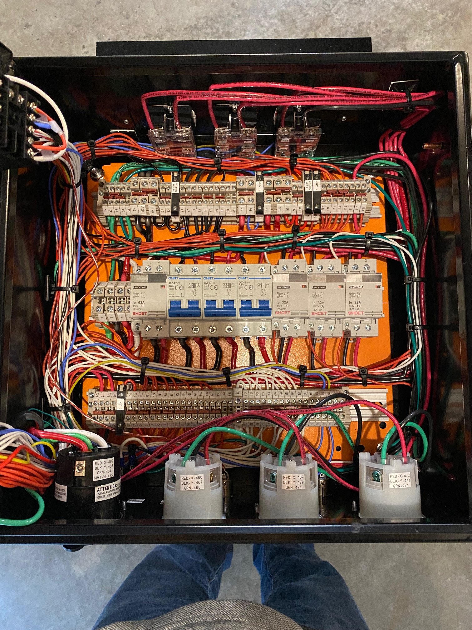
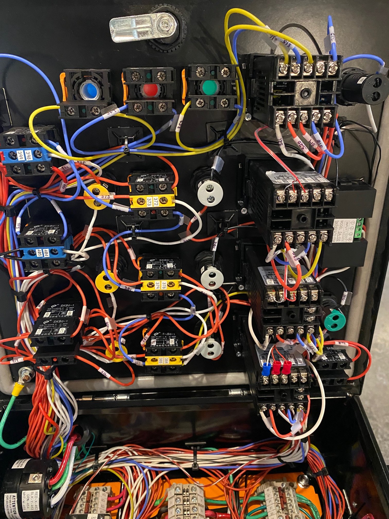
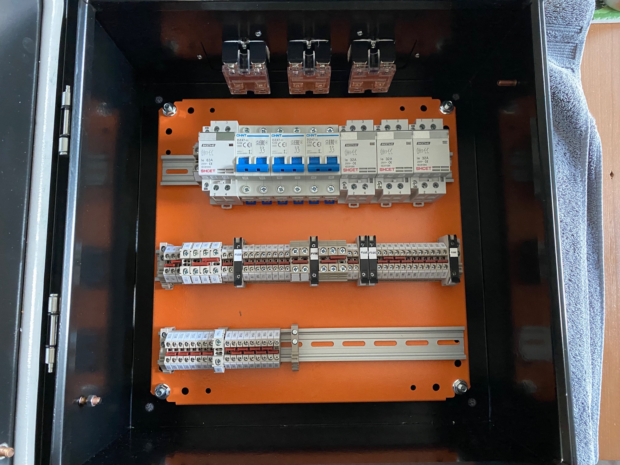
You are correct about the SSR control wiring for the HLT. Don't know how I got that one wrong, and the other two correct. Thanks for pointing this out. I will go back and correct.I believe I may have found a mistake on the drawing. I think the wires from the Auber DSPR3x0 to the 40A SSR for the HLT element are reversed. terminal 3 on the SSR should go to terminal 7 on the DSPR3x0 and terminal 4 on the SSR should go to terminal 6 on the DSPR3x0.
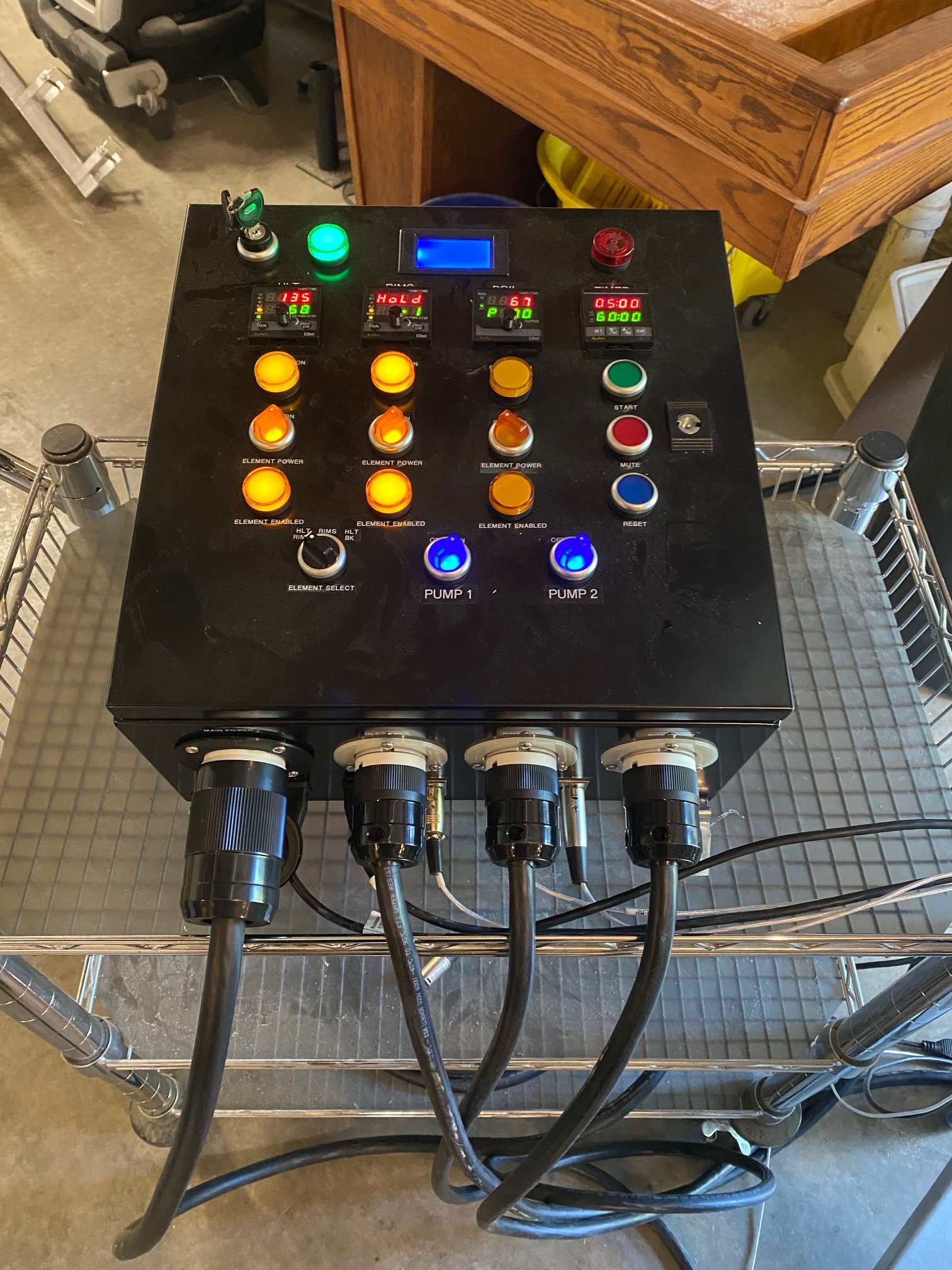
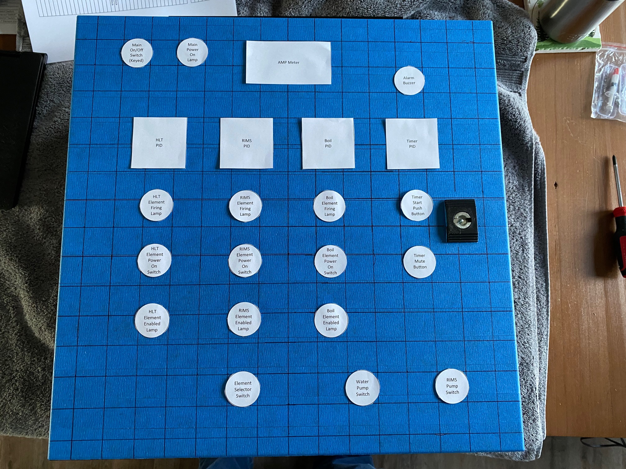
I have a question about the lamp on the element on/off switches. If the small red jumper on the right side was moved to the left side and the white wire on the left side was moved to the right side, would that cause the lamp to turn on indicating that switch would now be operational when the element selector switch was positioned to allow that particular element to be turned on? The light at the outlet for the element would then indicate when the element was actually powered on. I hope I'm explaining that clearly.
If you move the jumpers on the element enable switches, then the lamps will indicate when there is power to the switch, regardless of the position of the switch. As they are currently wired, they indicate when the particular switch is turned on AND the switch is receiving power from the "any 2 of 3 switch" - they let you know when power is actually enabled to the particular element. The lamps in parallel with the elements indicate when the elements are actually receiving power via the SSRs.
Brew on


![Craft A Brew - Safale BE-256 Yeast - Fermentis - Belgian Ale Dry Yeast - For Belgian & Strong Ales - Ingredients for Home Brewing - Beer Making Supplies - [3 Pack]](https://m.media-amazon.com/images/I/51bcKEwQmWL._SL500_.jpg)