• Please visit and share your knowledge at our sister communities:
  • If you have not, please join our official Homebrewing Facebook Group!

    Homebrewing Facebook Group

List of PJ Electrical Diagrams

Homebrew Talk

Help Support Homebrew Talk:

This site may earn a commission from merchant affiliate links, including eBay, Amazon, and others.
Pj, on my diagram you have 2 fuses. 10amp and 1amp. The 10 powers the PID and the 1 powers the pumps. Can I use 14g wire on these? Im having a bit of trouble heating up water in a test. The only thing i can guess is the 14g wire isn't amping it up enough.


Sent from my iPhone using Home Brew

ImageUploadedByHome Brew1401924915.704142.jpg
 
Pj, on my diagram you have 2 fuses. 10amp and 1amp. The 10 powers the PID and the 1 powers the pumps. Can I use 14g wire on these? Im having a bit of trouble heating up water in a test. The only thing i can guess is the 14g wire isn't amping it up enough.
Sorry but I cannot identify the drawing. The image you posted is way too small for me to read the ID info I add to the bottom right of the diagram. You would have been better off linking my original so that I (and others) could see it.
Also -
The 10 powers the PID and the 1 powers the pumps.
I think that is backwards.. Dont know as I cannot review the diagram. If what you say is true, I made an error drawing it. Please help me help you.

BTW: 14g wire is not the problem. It is more than enough to carry the current needed for both functions.


P-J
 
Clankenbrew,

It took me a little time to make the drawing for you but got it done. I also took the liberty of including pump control and outlets in case you change your mind or if someone else wants to use the plan.

As always click on the image to see and save a full scale diagram printable on Tabloid paper (11" X 17")


I hope this helps you.

P-J

Heres your post.


Sent from my iPhone using Home Brew
 
Yea... Your right I have the 1amp powering the PID and 10 to the pumps. I misspoke. I used 10g on the 10amp and 14 on the PID. My meter is broke so I cant check voltage until tomorrow but at last check i had 110 and 240 out to the outlets.


Edit:::: frikin harbor freight voltage meter.. Doi!
 
PJ -

You're diagrams are incredible. I am wondering if you would help me alter one?

Auberin-wiring1-a4-4500w-30a-e-stop-2.jpg


I want a push-button power button (SW11) that powers up the whole system. I'd also like 2 red indicator lights for the elements and a 3 way switch to switch between them (Boil - Off - HLT). And of course, an E-Stop.

I think I could piece it together, but I'd love it if there was a diagram to follow along with.

Thank you for contribution to the forums PJ!
 
Any one know if there are any PJ Diagrams using a SSVR and a POT? I'm looking to to also add a push button, like the SW1 to turn the unit on and off. Is a contactor needed for something like this? I'm not looking to use a pump at this time.

Thanks..
 
Any one know if there are any PJ Diagrams using a SSVR and a POT? I'm looking to to also add a push button, like the SW1 to turn the unit on and off. Is a contactor needed for something like this? I'm not looking to use a pump at this time.

Thanks..
The diagram in the post just above your request #426 has a SSVR and rheostat (POT) controlling the element.

Contactors are placed when a switch is used that cannot carry the current involved for the specific applicaion - as your need to use a SW1 to power the system on and off.
 
The diagram in the post just above your request #426 has a SSVR and rheostat (POT) controlling the element.

Contactors are placed when a switch is used that cannot carry the current involved for the specific applicaion - as your need to use a SW1 to power the system on and off.

Thank you sir!! If I were to remove the SW1 and replace it with a double pole switch...like a light switch, could I remove the contactor all together?
 
If your double pole switch is rated for the amperage / wattage of your system demand, then yes. Otherwise - no.
 
How does the rheostat work in that diagram? The ssvr is expecting 3-32vdc. The rheostat has no power going to it, only a ground. Must be missing something.

Also PJs diagram show the rheostat controling the element, without the pid. Could I put the rheostat between my pid and ssvr so the pid still controls the temperature, but I can use the rheostat to do less power for the mash or the boil?
The rheostat connected to the SSVR controls the percent of power delivered by the SSVR to its connected load. The SSVR is not expecting a variable voltage. It does not work that way.

Regarding using a PID along with the SSVR, I have no idea. In the diagram it is only controlling the rate of the boil.
 
I'm actually ready to start, been away from this project to long. Would it be possible to get a diagram to fit these components?

Goal is to control a 5500w element for HLT on 30A feed!

Items:
-40A SSR w/heatsink

-SYL2352 PID controller

-Two illuminated 120/240v switches from auberins ( one for main on/off, one for element on/off)

-Amico Overload Protection 2P+N Earth Leakage AC 230v/32A breaker

-Packard C230B 2Pole 30A Contractor w/120v coil

-NEMA L8-30-R 30A/250V Receptacle to plug the 5500w Element into

-XLR female plug for K-Type Thermocouple

-Panel Mount Fuse Holder


Sent from my iPhone using Home Brew
 
I just spent the last few hours pouring over this thread and can't help but thank P-J again, and everyone else that answers questions, for all the time and effort provided to help everyone make their systems work.

I hope someone here can help me with the last of the details I need to build my RIMS control box for a 120V system. All my breakers are 30A, in case that matters. I am using P-J's diagram: http://www.pjmuth.org/beerstuff/images/Auberin-wiring1-SYL-2352-basic6a-RIMS.jpg, as it is almost exactly what I am looking to build.

My system will use a burner to heat strike and sparge water and use the RIMS tube during the mash to maintain mash temps and again during fly sparging to maintain sparge water temps. Both of those will be run off the system as outlined in the diagram from the link. I have a two pumps, so the second pump switch will be used.

The major modification I would like to make is to add a second PID that will be used to monitor the temperature of the sparge water while heating it on the burner; I got two as a bundle from someone that got out of the game, so I figure I should use it if I have it. The PID will be connected to an alarm that will alert me so I can turn off the burner when the water reaches temperature. I would like the PID to be on the same kind of switch as what is in the diagram. I assume I wire the switch from the hot and neutral terminal blocks, and from the switch to a 1A fuse then to the PID. Is that all I need other than connecting the temperature probe to the PID?

Lastly, what gauge wire should I be using? I know that different runs can use different gauges, because the components have different draws. Can I wire this thing up using all the same gauge or do I need multiple different gauges?

Thanks in advance for any and all help!
 
I'm actually ready to start, been away from this project to long. Would it be possible to get a diagram to fit these components?

Goal is to control a 5500w element for HLT on 30A feed!

Items:
-40A SSR w/heatsink

-SYL2352 PID controller

-Two illuminated 120/240v switches from auberins ( one for main on/off, one for element on/off)

-Amico Overload Protection 2P+N Earth Leakage AC 230v/32A breaker

-Packard C230B 2Pole 30A Contractor w/120v coil

-NEMA L8-30-R 30A/250V Receptacle to plug the 5500w Element into

-XLR female plug for K-Type Thermocouple

-Panel Mount Fuse Holder


Sent from my iPhone using Home Brew

You can't use XLR quick connects for thermocouple sensors, you need to use the correct connector specific to your thermocouple type and K type thermocouple extension wire on the inside.

Like this:
http://www.auberins.com/index.php?main_page=product_info&cPath=7_43&products_id=119

The quick connectors can be used with an RTD sensor, though. If your not set on thermocouples for a particular reason I would recommend changing to RTD's since they are not really that much more expensive now.

And skip the panel mount fuse holder, just do an inline fuse or a fuse holder inside the enclosure. You really don't need it panel access, it's just one more hole to drill.
 
I'm going to give this thread a bump. this does not deserve to be on second page, rather should be in the sticky section.

P-J, you're a hero. Your knowledge is absolutely priceless!

I was wondering if I can run some things by you, P-J, and others on here. I'm slowly putting together a kit to automate my BIAB brewing. My current setup is a 10 gallon pot that sits over two electric stove top elements. I can get 8 gal of wort boiling no problem, but I'm thinking of putting an electric element to control mash temp better and get to boil quicker.

here's what I have so far:

1x 5500w camco element which I'm planning to use with 120v. 1375w should be plenty to maintain mash temp and be safe for 15amp outlet (right?)
1x SYL-2352 PID
1x 40amp SSR
1x K type thermocouple
1x 12v high temp 108gal mini pump which I use to recalculate the wort during mash. (http://www.amazon.com/dp/B007XZAJ3I/?tag=skimlinks_replacement-20)

The whole setup does not have to be anything fancy, no real need for on/off switches other then pump switch(12v), unless there are good (safety) reasons for it. I would like to have an e-stop button tho.

I'm looking for the best way to hook all of this up together.

Thanks in advance!
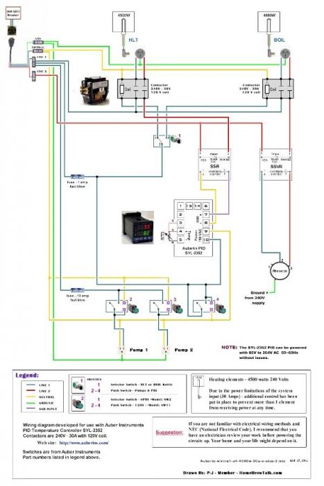

Was there a diagram for this setup?


Sent from my iPhone using Home Brew
 
Last edited by a moderator:
What size wire to the SYL2352 PID and from PID to SSR?
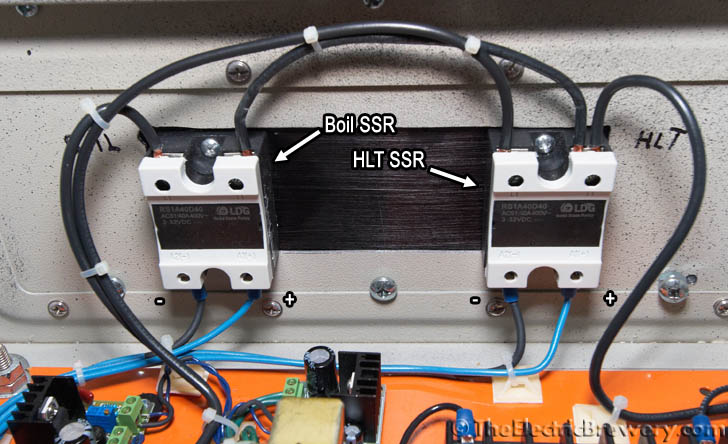
It's very low voltage/low current, so small 22 ga wire is fine. However, you may find it easier to attach something fatter like 14 ga. That's what I did. See the bottom blue wires attached to the SSRs:

IMG_6689_letters.jpg


I put some black shrink wrap on one the GROUND side just to differentiate/label.

Kal


Great thanks. Is there a requirement to have a fuse in line to the Contactor to protect that? Or will it be fine


Sent from my iPhone using Home Brew
 
You can if you like, but there's no specific requirement for it. You're building an experimental "home use" panel, so there's no requirement to do anything any specific way.

Kal
 
You can if you like, but there's no requirement for it, though I'm not sure what you mean by "requirement". This is something an experimental panel you're building yourself, so there's no requirement to do anything any specific way.

Kal


Thanks. Just wondering if it's needed to keep the component safe.


Sent from my iPhone using Home Brew
 
Nothing wrong with fusing absolutely every component (as some people do), but I feel it's overkill. It's a personal choice.

Kal
 
I have it wired, it works fine! The Overload Protection 2P+N Earth Leakage Circuit Breaker AC 230V 32A gave me a little issue! The other problem is the Auberins SYL-2352 is reading 55F lower than the Floating thermometer. I see there is a way to adjust the reading but are the RTD sensors the way to go? Or is it caused by location of thermocouple from element?


Sent from my iPhone using Home Brew
 
Are there diagrams like this for Gas setups? Looking to Add Asco Valves to my Brutus 10 Clone and want to run them with love tss2-21 switches. I have 2 pumps I will manually start and would like to have lights on at each pump and burner when it is active. A kill switch would be Cool as well....Thanks in advance for any input!

:mug:
 
The rheostat connected to the SSVR controls the percent of power delivered by the SSVR to its connected load. The SSVR is not expecting a variable voltage. It does not work that way.

Regarding using a PID along with the SSVR, I have no idea. In the diagram it is only controlling the rate of the boil.

Here's my control panel incarnation that I'm in the process of building which uses a PID (with relay outputs) to control an SSVR.
 
So I'm trying to electrify and set up in my basement (which has running water opposed to my shop which has a tank of water) and the basement has two 30 amp circuits running to it. One for dryer and one for water heater which is no longer in use.

I want to have a 240v element in each of HLT and BK. I'm trying to decide on HERMS and RIMS - I have a RIMS more or less available, would still have to purchase the HERMS coil. One 120v pump at present and debating on getting a 12v pump for RIMS and/or possible HERMS or spring for another Chugger or such. Still also deciding on BCS, Kal's, arduino, etc..

Lots of questions there, but first question is about the two 30 amp circuits. Can I run those into the panel rather than a 50 amp circuit, should I want to run both elements at once? I could install a 50 amp, but it would cost me the Spa panel and gfci breaker and about 40' of, I assume expensive, 50 amp cable, and 50 amp main circuit board breaker - vs. a couple gfci 30 amp breakers. (not an electrician but comfortable working with it - wired a few houses that passed inspections). I assume there is no problem doing this but thought I should ask what others would do.

Would like to just spring for a kit but due to budget, have to start slowly. /jd
 
I would say You only need 30amps since you'll not be using the HLT while boiling.
I use a 30amp circuit to a selector switch to active either contactor.
hope this helps.. Good luck.


Sent from my iPhone using Home Brew
 

Latest posts

Back
Top