
michaeltrego
Well-Known Member
I have been thinking about building a mini LED circuit board, rather than having individual large indicator lights. The reason is two-fold, to learn how to build one, and to have a different style of status indicators. The goal is to have 4mm light pipes (salvaged from an old cable modem) embedded in the panel door with a legend next to it.
Based on some research, I think I have two options for circuit design. The first is a half-wave, which may have noticeable flicker, and the second is a full-wave rectifier for flicker-free.
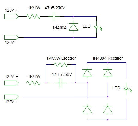
Are there any electrical engineers out there that can validate my approach and the component values? Has anyone done something similar? I have seen a lot of warnings about building LED connections to mains power, so I don't want to get hazardous, but with all of the 120V LED indicators on the market I figured it would be achievable if done carefully.
Based on some research, I think I have two options for circuit design. The first is a half-wave, which may have noticeable flicker, and the second is a full-wave rectifier for flicker-free.
Are there any electrical engineers out there that can validate my approach and the component values? Has anyone done something similar? I have seen a lot of warnings about building LED connections to mains power, so I don't want to get hazardous, but with all of the 120V LED indicators on the market I figured it would be achievable if done carefully.