Kal Style 120v e-herms panel

Homebrew Talk - Beer, Wine, Mead, & Cider Brewing Discussion Forum

Help Support Homebrew Talk - Beer, Wine, Mead, & Cider Brewing Discussion Forum:

This site may earn a commission from merchant affiliate links, including eBay, Amazon, and others.

sicktght311

Well-Known Member
Joined
Oct 16, 2018
Messages
684
Reaction score
303
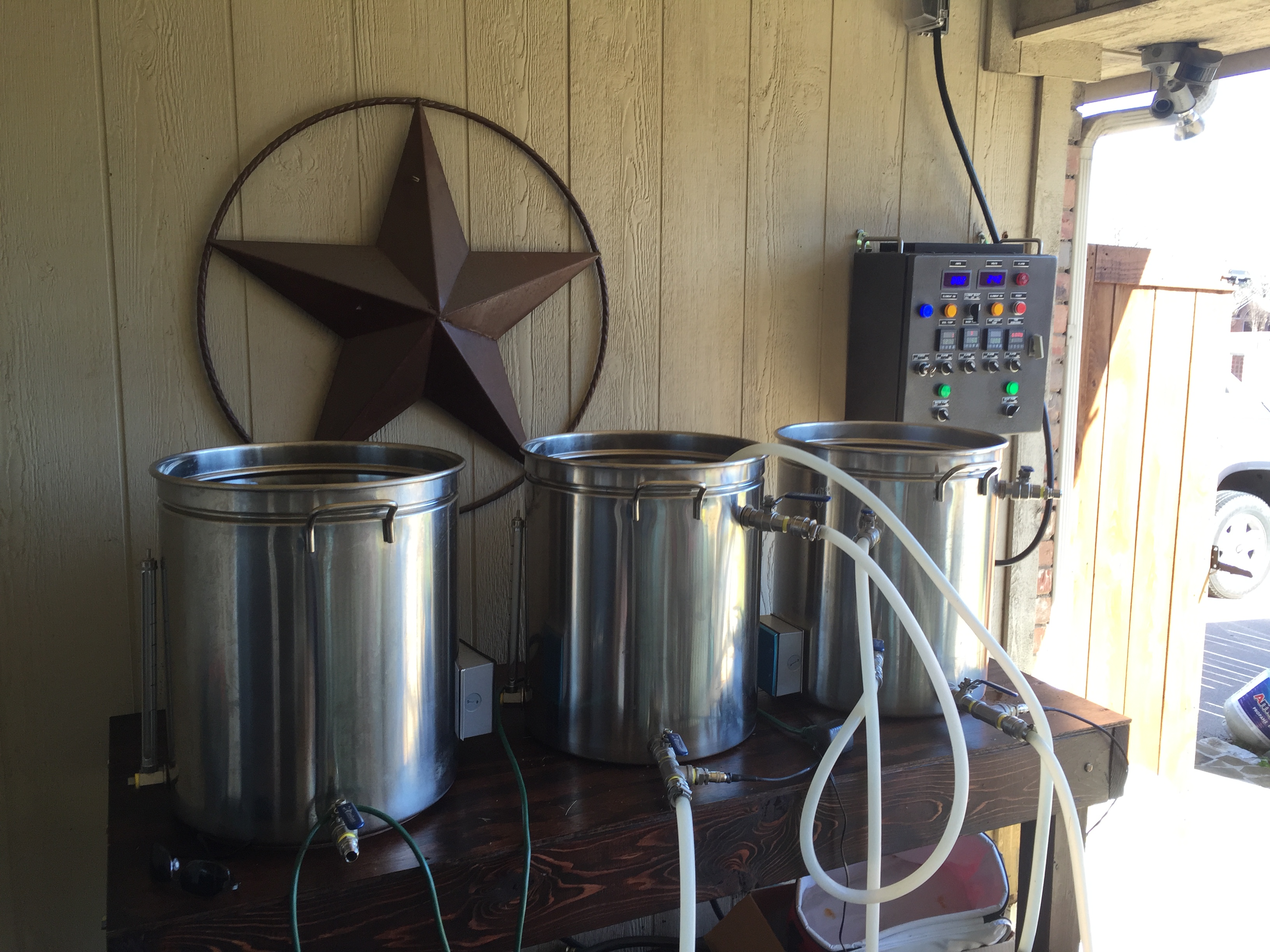
Anyone build one of their own? Show me what you got. This is the last piece of the puzzle in my 5gallon batch e-herms build. For now i'm running 2x Inkbird IPB-16s, one for the HLT/Mash control, one for Boil and temp monitoring while i whirlpool and chill. I'm running a single 1650watt element in the HLT, and a single 1650watt element in the BK, and before you start telling me to upgrade to 240v, no i dont mind the extra heat up times, and it boils just fine.

I like the overall "Complete" look of a fully dedicated 2 element/3 pid + Timer control panel, but have no plans to move to 240v until I upgrade to a much larger system, as running a 240 line in my basement would be a PITA and require me to completely rework my breaker since i already have an inground pool, hot tub, AC, etc. I'm currently using a 20amp extension cord to a 20amp outlet thats 15 feet away from my brew setup thats currently dedicated for my basement sump pump. Our basement sump pit is dry unless there's massive rains, so its something i can easily unplug and plug as needed.

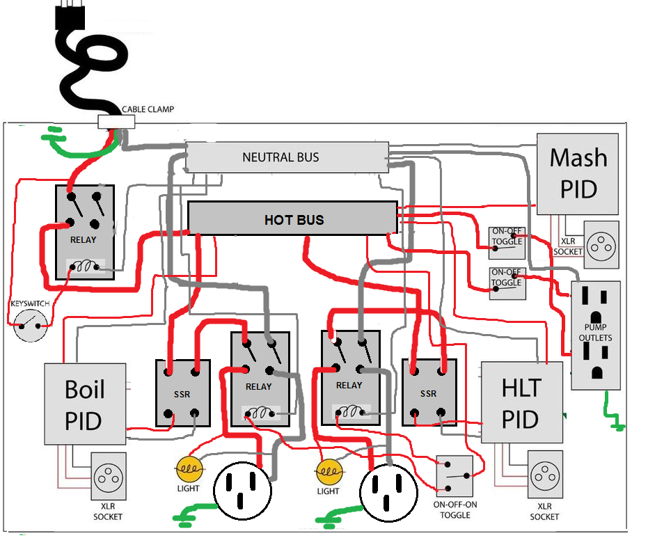
I'm fully up to speed and filled with knowledge of how the panels work from a usage standpoint, how the entire e-herms system works, etc etc, but I have yet to really dive into actually buying the parts and wiring up a 120v panel. I've done my fair share of wiring in the past, and i'm not afraid to build something, as its well within my skill set, i've just never researched why and what. Anyone have any experience? Ideally i'd want it to be exactly like the Kal/Spike panel, 3 Pids, one for mash temp monitoring, one for HLT control, one for BK control. Timer, element selector switch, 2x pump switches (I use a Mark II pump for the wort, and a solar pump for the HLT recirculation), etc.

First and foremost, is it reasonable to think that i could pretty much use any wiring diagram built for 240v, and just convert it to 120v outlets? Wouldn't the panel put out whatever voltage/amps is asked of it from the element, regardless of how its wired, so long as its within the total breaker amperage? I'm just thinking ahead because it would be nice if i could build a panel that's 120v ready with 240v gauge wiring, that way i would just swap out the receptacles for 240v in the future if i ever move to a larger system. As it is, both of my kettles were originally wired for 240v, so the 120v elements currently in them just reused the 240v gauge wiring with new plugs.

sorry for the novel, just wrapping my head around this, and you guys are the best resource!
 
If the 1650 watt element works for your setup I don't see a reason to move to a 240v system. I built a Kal clone a few years ago using the 5500 watt only because I was worried about wanting to do larger batches. Here is a picture of my setup.

Just build what you think will work best for you and what you think you will want to do in the future.
 

Attachments

  • IMG_0013.JPG
    IMG_0013.JPG
    2 MB · Views: 137
Yeah its not a question of moving up to 240v, or staying at 120v, i'm just trying to get some more info/advice about building a Kal clone that functions at 120v, but is upgradable easily to 240v for the future, and if building something with 240v in mind, can easily be adapted to 120v, or if they are completely different components outside of the wiring. 120v is more than enough for 10gallon kettles with 5gal batch size, but if i eventually move up to 20gal kettles or higher, 240v is required. And knowing me, i will eventually move up in size hah.
 
Most of the components are 120v. If I remember correctly everything wired after the contractors are 120v. I'd verify with someone more knowledge but I'd assume you can use all the same parts and it will only pull what power you plug into and what power the elements pull. When I was building everything out on my system I had the 30a/240v breaker hooked up incorrectly and it was only pulling 120. The box powered on and everything worked except for the 5500 watt heating elements.
 
Yeah my initial research tells me that other than the lower gauge wiring to accomodate 240v/30amps, and perhaps how things are wired 4wire vs 3wire, if a panel is plugged into 120v 20amp circuit, it will draw at most 120v 20amps, and thats what it will supply to the elements. If an element is under 20amps, it will only draw what the element requires of it.
 
Edit: My first reply I was thinking the OP wanted to run both BK and HLT simultaneously, but this in not the case.

All you really need is a pigtail with a 120V plug on one end and a L14-30 or 14-30 receptacle on the other end. The panel needs to be designed such that all 120V loads operate off of one hot line, and the all contactor coils are 120V and operate between the chosen hot line and neutral. Here is an example of how this can be done.

DSPR120 1-Pump 1-Aux Dual Voltage Input contactor.PNG


Brew on :mug:
 
Last edited:
How many gallons do you brew with a single 1650w element? Just curious because ive seen a lot of people complain that even a single 2000w element was not enough to achieve a boil on 6 gallons or wort and get proper boiloff but I know theres a few things that factor in this.
 
Edit: My first reply I was thinking the OP wanted to run both BK and HLT simultaneously, but this in not the case.

All you really need is a pigtail with a 120V plug on one end and a L14-30 or 14-30 receptacle on the other end. The panel needs to be designed such that all 120V loads operate off of one hot line, and the all contactor coils are 120V and operate between the chosen hot line and neutral. Here is an example of how this can be done.

View attachment 595594

Brew on :mug:

I think the biggest issue here is my current need for 120v input. As i mentioned in my first post, my dryer is hardwired, so i cant just unplug it and run a 240v extension cord, and my breaker is filled to capacity, so i'd need to have an electrician in to move everything around, and put in a new 240v line for the brewing panel..........So for now, i'm only looking to have the input power at 120v 20amps. If i had a 240v line nearby, i'd just run 240 elements and panel and be done with it
 
How many gallons do you brew with a single 1650w element? Just curious because ive seen a lot of people complain that even a single 2000w element was not enough to achieve a boil on 6 gallons or wort and get proper boiloff but I know theres a few things that factor in this.

5 gallon batches. Boil isnt a problem if you dont brew in a cold garage, and you keep the lid on slightly cracked. I was doing 3.5 gallon brews on my electric stovetop for a while and to get that to boil you had to have the lid on cracked, and i never picked up any off flavors. No DMS problems so long as you still have the lid cracked enough to vent the steam. You can also wrap in reflectix which helps immensely. I agree if you have a lid fully off though, achieving boil is difficult.
 
I think the biggest issue here is my current need for 120v input. As i mentioned in my first post, my dryer is hardwired, so i cant just unplug it and run a 240v extension cord, and my breaker is filled to capacity, so i'd need to have an electrician in to move everything around, and put in a new 240v line for the brewing panel..........So for now, i'm only looking to have the input power at 120v 20amps. If i had a 240v line nearby, i'd just run 240 elements and panel and be done with it
The point of my post was to show how to make a pigtail that will allow a 240V panel (that meets some internal wiring constraints) to plug into a 120V outlet. Isn't this what you are wanting to do?

Brew on :mug:
 
The point of my post was to show how to make a pigtail that will allow a 240V panel (that meets some internal wiring constraints) to plug into a 120V outlet. Isn't this what you are wanting to do?

Brew on :mug:
Ah then maybe i misunderstood. What i thought you meant, was plugging a 240v panel into a 240v supply, and then having the element and pump plugs output at 120v. Interesting. So i can pretty much then utilize any 240v panel, buy a pigtail adapter, plug it into the outlet, and i'm good to go?

1x outlet of a 2 outlet 20amp gfci wall socket-->Extension cord to brew area-->plug into one side of the pigtail--->Pigtail plugs into 240v input on panel = Panel operates at 120v supplying full 120v power to the element?
 
Correct. But internally the panel must meet the following constraints:
  1. All 120 loads must be powered by the same hot leg of the 240V, and the pigtail must provide voltage to that hot leg of the panel.
  2. All contactors must use 120V coils, and these coils count as loads for rule #1
  3. You should use 240V indicator lamps for the "Element Firing" lamps. They will still light at 120V, but will be dimmer. If you used 120V indicators, they might blow when run at 240V.
If you buy a pre-built panel, then you would have to reverse engineer it to make sure it meets the above requirements. If you build your own, you just need to check the design information. If you don't fully understand what was said above, then you need to find someone who does to help you.

Also, I'm not sure you can buy this type of adapter pigtail. You probably have to wire it yourself.

Brew on :mug:
 
Ok so i'm finalizing my plans on this. I decided i want to go with the simplest solution, as i'm trying to keep costs down, as this is designed for 120v, and i'll put the full massive work into a 240v panel if i end up upgrading my brewing size.

What i want is 2 auber ezboil pids, one for the HLT herms to mash tun output temp control, and one for boil kettle. 2 120v pumps, and an element select switch (to ensure only one is on at a time). Simplest design possible..... i can basically double the Rims controller diagram below (replacing the input with a 20amp circuit, and the elements at 1650watts), and then swap out the single switch and wire in a 3 way switch between the two different element SSR low voltage leads, thereby allowing only current to the selected SSR, correct? I can even go as far as to use a lighted switch for the element selector, and pump switches, saving space, and letting me know when everything is on/firing. Trying to fit this into a small form factor, preferably 8x10. I know others say using a contactor as a backup incase the SSR fails in the on position is smart, but if one element SSR fails, it would most likely be while another element is firing, and it would pop the breaker due to overcurrent. So the breaker itself would be my failsafe.

maxresdefault.jpg
 
Upon second thought......i'd more likely need a switch that can handle a 120v 20amp load, and have it on the hot wire SSR's, and split the signal from there between the two SSRs. Thoughts?
 
Do you have a electric dryer? what is wrong with plugging into that with the correct size wire?
 
Upon second thought......i'd more likely need a switch that can handle a 120v 20amp load, and have it on the hot wire SSR's, and split the signal from there between the two SSRs. Thoughts?

Yes switch on a hot 120V SSR wire has much more sense. But why do you need second SSR?
 
Yes switch on a hot 120V SSR wire has much more sense. But why do you need second SSR?
Two elements. One in the HLT, one in the Boil Kettle. Separate Pids, separate temp probes. Just want it all in one panel, with element selection switch to make sure only one is firing at a time
 
On further inspection, it seems a 120v On/Off/On switch that could handle a 20-30amp load, is expensive and tough to find. I mostly find switches designed for selecting power input for a boat (shore vs Gen power).

Based on this, i've built the following (horribly crude) diagram for a 120v controller. The Mash Pid is purely for monitoring temperature, and can be optional if i decide to just stick with a single pid for HLT Herms Coil exit temp only.

Critique away. I'm sure this is completely wrong.

zpPNM80.png
 
Apologies for the millions of replies to this. I appreciate everyone help in advance.

Modifying above, I should be able to declutter some of the Neutral lines by connecting the two contactor inputs together daisy chained, PIDs neutrals daisy chained, etc.

For the relays, i figured might as well run 240v DPST 30amp 120v coil relays that i'd normally use for a 240v system, and just pass both the hot and neutral lines through for simplicity sake. This way, if i ever decide to upgrade my system to full 240v, i can reuse the relays, SSR's, PIDs, etc and upgrading the panel to 240v should be fairly simple
 
On further inspection, it seems a 120v On/Off/On switch that could handle a 20-30amp load, is expensive and tough to find. I mostly find switches designed for selecting power input for a boat (shore vs Gen power).

Based on this, i've built the following (horribly crude) diagram for a 120v controller. The Mash Pid is purely for monitoring temperature, and can be optional if i decide to just stick with a single pid for HLT Herms Coil exit temp only.

Critique away. I'm sure this is completely wrong.

zpPNM80.png
This looks like it should work. Personally, I like to put the contactors (relays) upstream of the SSR's, just so when they are open, fewer things have voltage on them in the panel.

Apologies for the millions of replies to this. I appreciate everyone help in advance.

Modifying above, I should be able to declutter some of the Neutral lines by connecting the two contactor inputs together daisy chained, PIDs neutrals daisy chained, etc.

For the relays, i figured might as well run 240v DPST 30amp 120v coil relays that i'd normally use for a 240v system, and just pass both the hot and neutral lines through for simplicity sake. This way, if i ever decide to upgrade my system to full 240v, i can reuse the relays, SSR's, PIDs, etc and upgrading the panel to 240v should be fairly simple

To be 240V ready, you should also switch the neutral with the main power relay. And, since you are using a main power relay, you could add a "safe start" interlock that prevents main power from being turned on unless all element and pump switches are off. Requires additional switch blocks on the element and pump switches.

Brew on :mug:
 
Doug has spoken! Thanks Doug. Looks like i'll have to start acquiring some parts. Seems like the hardest part is finding an enclosure.

For 120v, i'm sure i could go with a plastic enclosure since the heat generated by a 13.75amp 120v element has to be pretty low, and with a heatsink i shouldnt have any concerns about overheating the enclosure, but if i can find something metal, for a reasonable price, thats a win win.
 
Plastic is fine, even at 240V. Most of the heat in the panel is generated in the SSR, and worst case heat dissipation for an SSR, at even 23A, is about 35W. A properly mounted heatsink can easily take care of the 35W.

Let me know if you are interested in how to implement the "safe start."

Brew on :mug:
 
Back
Top