johnnybrews12
Active Member
- Joined
- May 16, 2018
- Messages
- 33
- Reaction score
- 9
Hey all,
I just moved into a new apartment (renting). My last apartment had easy access to a 30a 240v dryer plug. This new apartment, not so much. I have tried moving my washer dryer unit but it is jammed into a closet and is stacked. No way I'm getting it out.
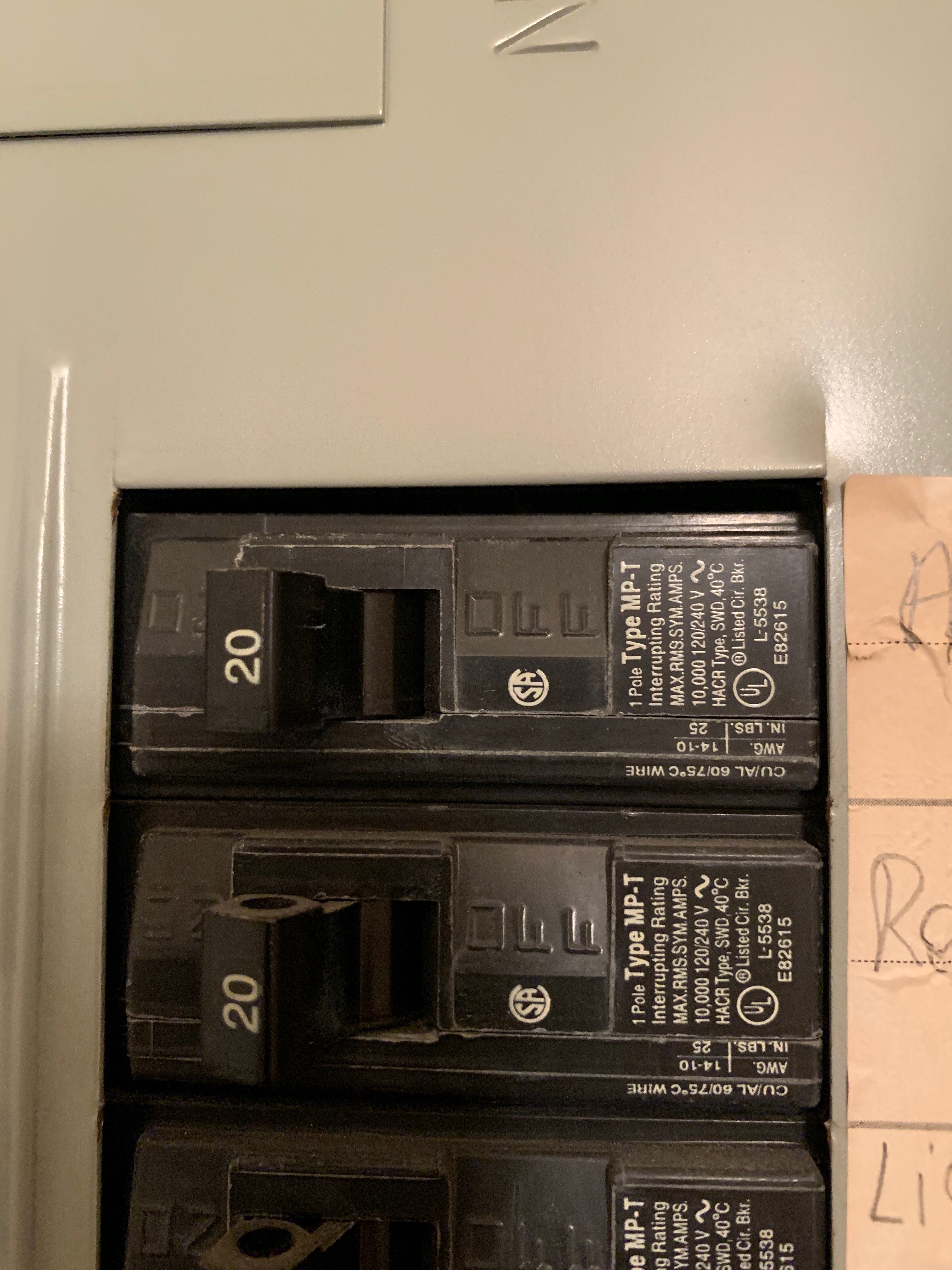
I found a 3 prong outlet in my bedroom that I assume is for an air conditioning unit. After checking it out, I found that it has 2 hot legs going to 2 separate 20a breakers. Measuring across the hots I get 240v.
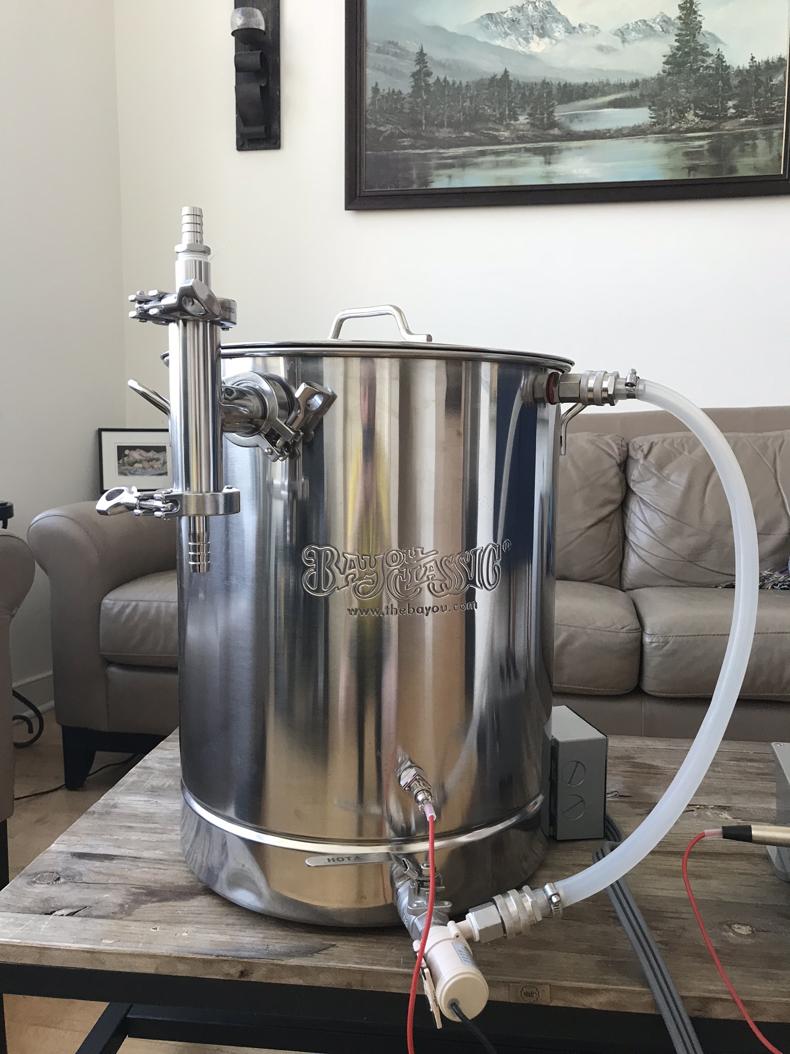
My system is a 15gal EBIAB with a 3500w (it actually may be 4500w but I cannot remember for sure at the moment, will have to look into it) heating element. At the old apartment, I ran a plug from the dryer outlet to a spa panel/gfi and then to my control box (4 wire configuration H-H-N-G).
What are my options here? Can I do anything with the air conditioning outlet? Am I **** outta luck? Bite the bullet and start designing a new system that uses 2 elements and 2 outlets on different 120v circuits? That would be the last thing I'd want to do because ...money. I've been racking my brain over this for the past week at this point.
I just moved into a new apartment (renting). My last apartment had easy access to a 30a 240v dryer plug. This new apartment, not so much. I have tried moving my washer dryer unit but it is jammed into a closet and is stacked. No way I'm getting it out.
I found a 3 prong outlet in my bedroom that I assume is for an air conditioning unit. After checking it out, I found that it has 2 hot legs going to 2 separate 20a breakers. Measuring across the hots I get 240v.
My system is a 15gal EBIAB with a 3500w (it actually may be 4500w but I cannot remember for sure at the moment, will have to look into it) heating element. At the old apartment, I ran a plug from the dryer outlet to a spa panel/gfi and then to my control box (4 wire configuration H-H-N-G).
What are my options here? Can I do anything with the air conditioning outlet? Am I **** outta luck? Bite the bullet and start designing a new system that uses 2 elements and 2 outlets on different 120v circuits? That would be the last thing I'd want to do because ...money. I've been racking my brain over this for the past week at this point.
")


![Craft A Brew - Safale S-04 Dry Yeast - Fermentis - English Ale Dry Yeast - For English and American Ales and Hard Apple Ciders - Ingredients for Home Brewing - Beer Making Supplies - [1 Pack]](https://m.media-amazon.com/images/I/41fVGNh6JfL._SL500_.jpg)