• Please visit and share your knowledge at our sister communities:
  • If you have not, please join our official Homebrewing Facebook Group!

    Homebrewing Facebook Group

I need a single PID, single element diagram

Homebrew Talk

Help Support Homebrew Talk:

This site may earn a commission from merchant affiliate links, including eBay, Amazon, and others.
gigapunk said:
Thank you for the help guys, I've spent some time reading about AC current trying to learn as much as I can.

So in the above schematic with a neutral and one hot 220v lead going to the PID, is the PID then powered by 110V (even though it does not have a second hot lead)? Could the PID alternatively be powered by two hot leads to 9 and 10?

If the PID is designed for 110v it could hurt it to power it with 220v. The diagram that was provided above is great for what you are trying to do. It provides 220v to the heating element and 110v to the controller. If you follow the line diagram you should be ok.
 
To hook it up without a neutral you will need a 220v PID. Then you will be able to hook it up from the available dryer plug.
 
Thanks for all the help guys! This stuff is finally making sense.
 
I need a wiring too,please. I have 2 5500 watt heaters on 240.. I have two 1/2 hp pumps. These need to be controlled as two seperate pump and heater combos. I have 2 Sestos B2E timers and 2 Sestos D1S controllers.Timer 1 and controller 1 work together. Timer 1 will tell controller 1 when to shut down. It will also time a pump on simple on/off. I need an indicator light light between Timer 1 and pump. I need indicator light between Controller 1 and heater 1. Setup 2 is identical to Setup 1, mounted in same control panel. This is a biodiesel processor. Pump 1 and Heater 1 are on a 100 gal conical steel tank circulating from bottom to top. Pump 2 and Heater 2 are on a 55 gal drum circulating from bottom to top.
 
I need a wiring too,please. I have 2 5500 watt heaters on 240.. I have two 1/2 hp pumps. These need to be controlled as two seperate pump and heater combos. I have 2 Sestos B2E timers and 2 Sestos D1S controllers.Timer 1 and controller 1 work together. Timer 1 will tell controller 1 when to shut down. It will also time a pump on simple on/off. I need an indicator light light between Timer 1 and pump. I need indicator light between Controller 1 and heater 1. Setup 2 is identical to Setup 1, mounted in same control panel. This is a biodiesel processor. Pump 1 and Heater 1 are on a 100 gal conical steel tank circulating from bottom to top. Pump 2 and Heater 2 are on a 55 gal drum circulating from bottom to top.
Sorry: Would like to help with a drawing - however - your build plan is based on Sestos components. I'm not familiar with them and it poses a sharp learning curve for me that I'm not willing to invest in.

Auber Instruments components - no problem..

Again, sorry...
 
vegoiltycoon said:
I need a wiring too,please. I have 2 5500 watt heaters on 240.. I have two 1/2 hp pumps. These need to be controlled as two seperate pump and heater combos. I have 2 Sestos B2E timers and 2 Sestos D1S controllers.Timer 1 and controller 1 work together. Timer 1 will tell controller 1 when to shut down. It will also time a pump on simple on/off. I need an indicator light light between Timer 1 and pump. I need indicator light between Controller 1 and heater 1. Setup 2 is identical to Setup 1, mounted in same control panel. This is a biodiesel processor. Pump 1 and Heater 1 are on a 100 gal conical steel tank circulating from bottom to top. Pump 2 and Heater 2 are on a 55 gal drum circulating from bottom to top.

I have a sestos timer in my build so I'm familiar with that. I can answer questions if you have them. As for the other components, I am not so sure of since I used auber pids
 
Sorry: Would like to help with a drawing - however - your build plan is based on Sestos components. I'm not familiar with them and it poses a sharp learning curve for me that I'm not willing to invest in.

Auber Instruments components - no problem..

Again, sorry...

P-J, I bet you have a drawing already with Auber PIDs and timers that would get him most of the way there. ;)
 
Very true - however the differences between the Auber and the Sestos is huge. Very difficult to even try to interpret a chang in a plan.

Understood. Just draw a cloud around each PID and timer and show the connections in and out of it, lol.

Incidentally, I'm kidding around, and don't expect you to draw anything you don't want to draw. You do enough around here already. :)
 
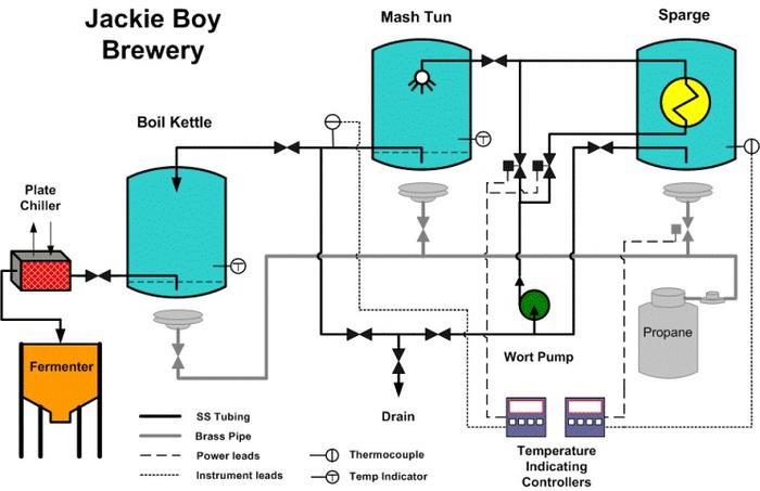
I would like to build this but use a 220 volt heating element to fire the HLT and a PID to control it instead of the propane. The mash tun will be a 10 gallon water cooler. The HLT will be a 15 gallon kettle. I'm going to use a 220 volt induction cooktop and a 15 gallon kettle for the boil. I may just do a gravity feed for the sparge.

Is there a diagram that can help me out with the wiring of the electric controls for this situation?

image.jpg
 
P-j is there a reason there is no relays or contactors for the input power or the power to the elements. Every other one I have seen uses relays with 120v coils. Namely the diagram from the electric brewery. Is there a reason to use or not use them.
 
P-j is there a reason there is no relays or contactors for the input power or the power to the elements. Every other one I have seen uses relays with 120v coils. Namely the diagram from the electric brewery. Is there a reason to use or not use them.

It looks like in the diagram there he's using just a DPDT switch that's rated for the 30A, but you can switch that out for a contactor + switch of choice.
 
It looks like in the diagram there he's using just a DPDT switch that's rated for the 30A, but you can switch that out for a contactor + switch of choice.

I looked up that switch and it is only rated to 15amps at 250v. I read on the electric brewery that they use them for safety so there is no way power can get to the elements of the switch is off also it says the switches are not rated to take the current. Check these links out and tell me what you think.
http://www.theelectricbrewery.com/control-panel-part-2?page=13

http://www.theelectricbrewery.com/control-panel-part-2?page=7
 
I looked up that switch and it is only rated to 15amps at 250v.

You are right, I just went to that Grainger part number and see it's only 15A at 240v, 25 if using for 120. So that one wouldn't be good for switching a 5500W element. I'm having a hard time finding one for some reason, but I know you can get properly rated ones even at Home Depot. Or you can use a contactor. Either way works as long as your components are rated for the current. Definitely have a switch on the element, it's handy. With how cheap contactors are I'd just role with one of them and a switch of choice.
 
I'm not seeing it on the diagrams earlier this thread, but sounds like part of his e-stop design. Trips the GFCI breaker.
 
I'm not seeing it on the diagrams earlier this thread, but sounds like part of his e-stop design. Trips the GFCI breaker.

It was this one
http://www.pjmuth.org/beerstuff/images/Auberin-wiring1-a4-5500w-30d.jpg
 

Latest posts

Back
Top