I decided to start building a brewing system

Homebrew Talk - Beer, Wine, Mead, & Cider Brewing Discussion Forum

Help Support Homebrew Talk - Beer, Wine, Mead, & Cider Brewing Discussion Forum:

This site may earn a commission from merchant affiliate links, including eBay, Amazon, and others.
Just wanted to share a bit about the think process regarding the programming and creation of the controller.

The idea that I am working with now is to have a very simple interface and interaction with the user (which at the moment would be me and SWMBO).

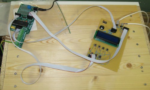
So...4 buttons is all that is required....did however add 3 more buttons, just in case I will do some future improvements later on.

When the controller is powered on, it will automatically go into a setup stage, with default settings that doesn't need to be changed unless you would like to brew special types of beer.

First setting is HLT delta temperature setting (i.e. how much hotter should the HLT be than the MLT).

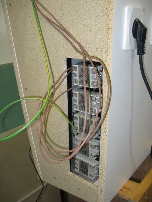
Second setting allows the user to configure how the HLT effect steps should be used in the modes HI, MED, REG(ulation). E.g. user can have 3 separate heating elements in "HI" mode and only use 1 for "REG" mode.

Third setting is to set/confirm the different MLT rest temperatures.
Currently have 4 steps defined with the default values:
Rest 1: 50 C (122 F)
Rest 2: 60 C (140 F)
Rest 3: 68 C (155 F)
Rest 4: 78 C (172 F)

That's it....when this third setting is done, the user is taken into pre-runtime mode where a "Water in HLT?" confirmation is needed.

When in runtime (i.e. when brewing) it's easy to switch between the different rests.
 
How about fermenting in those large barrels? How's that working? How do you clean them after use and sanitize before use?

Impressive project!
 
Fermenting in them works very well. Leaves no plastic taste what-so-ever, so that is good.
The lids are fitted with a O-ring so when the stainless ring is tightened around the lid it's super tight.

For cleaning I use either just water or water with some dish-washing soap.
Then I use a spray bottle with iodine in pretty high concentration and spray the inside of the barrel and let it sit for a few minutes until it's rinsed well with water.
 
Back after a one week business trip to India (where you btw need to look way harder than I did to find any IPA:s). Did however find a brew pub in Guragon - just outside of Delhi. http://www.gurgaonsite.com/rockmans-beer-island-in-gurgaon.html
Tried their brews (only lagers and a weissbier). It tasted marginally better than the domestic beers Kingsfisher and Tiger....which don't taste much at all.

Once my stomach settles down from the indian food, it's time to make another brew. This time I will use the controller that I have programmed. Will post pictures.
 
It's really good to see this system working, Grattis!
I wandered through the posts to see what volume your system was putting out. Went back to the first post 120L, Wow!

I have two questions. I take it you're not bottling. Are you keeping one batch in 20 cornies?

And, one 2kw element heated up 120L of water to boiling?

I'm thinking of going electric but can not do the stuff with SSRs and PIDs and electronic displays and circuit boards and all that dark magic. Thinking of plonking an element into a 30L food grade barrel.

Hi.
You are right, I don't bottle.
Never done a "full batch" yet. Normally do 15 Gallon batches.

I guess you could use a 2 kW element for getting it to boil - but it would take quite some time. I have a 6 kW element (3x2 kW) in the boiler. Then I go on full power until I get boil and simply turn off 1 or 2 elements to keep a rolling boil.

But for a 30 liter barrel, 2 kW should be ok and remember the more you insulate the barrel, the faster it will heat.
 
I was thinking about starting a new thread for this next inline project of mine - as I guess that some people get a bit bored of reading through my thread on here...but decided to stick to this one.

So let me tell you about this new thing that I have in the thinking process.

Background: As I have mentioned, we have built a house. What I haven't mentioned is that we have "rock heating" in our house.
Don't know how common that is in the US (or even if it is called "rock heating" as that would be a direct translation) but the principle is like this:
-Drill a hole down into the rock. In our case we drilled 197 yards.
-Since the temperature in the water that you hit in the rock always is above freezing point you can use that in combination with the suitable media in liquid/gas states to extract heat with minimal power

bergvarme.JPG


The thing is, as the temperature down in the hole is pretty much constantly around 8C (46 F) this would be perfect to be used for cooling the beer.

So when my SWMBO's parents were here this weekend I asked her dad (the plumber) if this was possible to do and he replied that not only was it possible to do, but also to do it without costing too much. as we already from the beginning planned to use "free cooling" (i.e. cooling of the house in the summertime without a need for an air conditioner).

So this will be the next big project in the beer brewery of mine...and additionally this will be an environmental friendly thing to do, and at the same time I will gain in less cost for the heating of the house.

So in conclusion:
Cold beer and lagering
Cold house in the summer
Less cost for heating.

So it's a win win win situation!
 
I think the US equivalent of Rock Heating is Geothermal heating. It is a newer technology here, but it does seem like I am seeing more geothermal companies popping up.
 
Yeah we have it over here. Not real common but more people are going with it as a "green energy" option. They call it Geothermal heating. If I ever get to build my dream Pro Brewery I am doing this!
 
The "geothermal" heat pump systems have been around quite a while, two methods in use open loop (water in-out to drain) and closed loop with circulating coolant. Largest system I have designed and was built was a 100 ton unit for city of salem, used city water for the source/sink and called the water usage system losses at 600 GPM. On the small side was 4 - 5 ton water to air units using well water as a once through to drain or sprinklers in summer. Those units were happy with about 8-10 GPM of 56 degree ground water. The closed loop systems around were slant bored holes with freon tubing buried in hole with a bentonite mix to backfill as the bentonite swells when rehydrated. They worked fairly well in heating mode but some had problems with fill material dehydration during cooling when tubing got hot.
 
I haven't been able to do any brews yet...it has been too hot here for fermenting with the results that I want. That and the fact that I am building a 1500 sq feet deck (future pool deck and porch).

But don't be alarmed (regarding the building process) I am ensuring that there will be a permanent installation so that we can get nice cold beer poolside.
 
Am I the only one seeing a problem with this here, noticed you said you had your plumber do inspections, shouldn't you let your electrician do the same :) Doesn't look safe to this electrician (me)
power_HLT.JPG

Perhaps rigging these (ip55 box (the first number of the IP number is the protection against dust, range from 0-6. the later one is water protection ranging from 0-8) on the back of the elements to be on the safe side and have the cables go out. Or covering them with silicon?
AP9g_W4.jpg
 
Am I the only one seeing a problem with this here, noticed you said you had your plumber do inspections, shouldn't you let your electrician do the same :) Doesn't look safe to this electrician (me)

Perhaps rigging these (ip55 box (the first number of the IP number is the protection against dust, range from 0-6. the later one is water protection ranging from 0-8) on the back of the elements to be on the safe side and have the cables go out. Or covering them with silicon?

In the "permanent" set-up, the power cables to the heating elements are completely covered and I have lids over the cut-out squares where the heating elements are, making it hose/drip safe.

But I actually think that I will go ahead and also silicone seal the power cable to the elements as that would be like an inner seal.

European_Type_AC_PC_Y_Power_Cord_Cable.jpg


The whole setup is also connected to a ground-fault circuit interrupter (GFCI) in case there would be an imbalance in the current flowing between L and N.

But....even if a construction like this never would pass a formal CE inspection, it currently feels more secure than the actual water heaters that I got the heating elements from.
 
Awesome build DrKarma.

Are there any reason why you should not use the same plastic containers as a boiler?
 
Awesome build DrKarma.

Are there any reason why you should not use the same plastic containers as a boiler?

Well I could have, but since I wanted to use heating elements with good ummpf in the wort boiler...I decided to go for the same type of heating elements that you would find in a boiler for hot water in homes.
Those have a R50 (2") fittings, and mounting them in the plastic containers would be a real challenge.
 
Brewday tomorrow and this time I will use the temperature controller that I made. It has been ready for quite some time now, just haven't found enough spare time to do any brews for the last month or two.

I did a water test in the eHERMS system today.
Noticed that even though I only pass around 8 amps through the 25 A SSR, they still get quite warm. Might fit a fan into the control unit as well.

Another reason why I did a water test today is that I finish it with getting everything up to boiling point so I get rid of whatever bacteria that is in the piping etc before I do a brew.
 
Weather sucks today so I stay indoor brewing instead. Here you can see the setup with the temp controller connected.

 
Last edited by a moderator:
scenes from a brewday.

As I brought the laptop with me to the brewery, I will post some pics every now and then during the day.


Todays brew requires 26 pounds/13 kg of barley

korn.JPG


Still havent come around to fixing a false bottom, so I use a manifold.

manifold.JPG


This is where the magic happens. The Controller and the DUI (Digital User Interface). These will be built in somehow.

controller.JPG


The outlets that the controller box control
bigbox.JPG


Before you start to talk about how unsafe this looks, then know that these wires are for 5 V only....and it's a very temporary setup.
ssr_s.JPG
 
Protein rest


If you rather would like to see the picture...

protein_rest.JPG
 
Last edited by a moderator:
I think the US equivalent of Rock Heating is Geothermal heating. It is a newer technology here, but it does seem like I am seeing more geothermal companies popping up.

It's also called "ground source" around here (IL). Same thing, same implementations. We know people who just had one installed. Given the current LARGE break on such a system in Federal taxes, you're looking on maybe a 5-7 year payback here in the Midwest. So if someone were planning on staying in their current house that long, it's a no-brainer.
 
Next expense in the system will be to have a tight fit "bucket in bucket" or mashing basket that I call it. It will be made out of stainless steel. It will have a perforated bottom (3 mm holes).
Purposes are:
1. ability o lift the basket up in case of a stuck manifold during recirculation
2. as the system I have is fairly big, it's a time consuming event to clean it after brewing. This way I will just lift the basket up and carry it to the compost.
3. I want to have a mash stirrer/mixer in the system to get even temperature even faster than the normal HERMS does.

These are the drawings that I have sent to my welder (I still haven't started to build my competence in the stainless steel welding area so for now I have to spend extra money on it)

m%E4skkorg_ovan_small.jpg


m%E4skkorg_under_small.jpg


m%E4skkorg_inbuktning_small.jpg


You will have to imagine the bottom plate as it took too much CPU to create 1000s of holes in Sketchup. :)
 
You can simulate the holes in the bottom with a transparent texture similar to the chain link material that is in Sketch-up. If you wanted to.

Like this:

MLTScreen.jpg

MLTScreen-2.jpg

Let me know if your interested and I will send you the image I created for the material.
 
The welder was too expensive and let's face it...how much DIY would it be if I would have a welder do it?

Instead I decided to buy myself a christmas gift - an ESAB Caddy 160 with the complete setup for TIG welding (Argon Gas, and TIG burner etc)

I also found an add for a stainless expansion chamber that I bought (had the right diameter).

expansion_chamber.jpg


Then after some work with the angel grinder and the TIG welder the result turned out like this.

filterkorg_1.jpg


And this

filterkorg_2.jpg
 
Latest addition to the brewing system is a plate heat exchanger. Not so much DIY as I got it from a fellow brewer. Took me about 30 seconds to decide that I would retire my huge IC.

plvx_bild.JPG

The heat exchanger has back ports for one of the flows (wort flow) that I will use to temp probe in temperature and out temperature (out temperature is really the only that I need) so I can regulate the chilling (tap water) flow.

Spec: 5000-7000 W/m² ºC
 
I had to call in sick two days ago, caught a "man cold", you know...when it feels like someone is ice fishing with barb wire in your throat. (Well I bet that men reading this understand, women - to my knowledge never seem to get colds like these).

Anyway...For those of you that read my thread, you have seen the fairly big MLT that I have and the mashing basket that I have created for it.
Well, it works fine, but even if the cleaning process is much quicker than before, I still would like something that makes it even faster.

I also believe that I have mention my intention to build one smaller system that I can use for tweaking and experimenting with recipes.
Hence the birth of my MLT v2.0 that will be one of the new components to my brewing system.
The thing is that I want to have a modular system so I can replace the big MLT with MLT v2.0 whenever I am brewing a smaller batch - so the only parameter I change is the actual MLT.

During my terrible man cold, I got a bit tired of sleeping and resting so I went out to the garage and started working on it.

The donor for this project is a Coleman 40 Qt cooler that I bought some years ago when I lived in Dallas. Great in the GC where I lived to bring cold beer to the pool. But back in Sweden it has not been used much at all as it is too big to bring with you when you go picnicking or hiking.

coleman_40_Oz.jpg
 
I began with removing the draining cap and fitting from the cooler. Measured the hole and noticed that it was a bit too wide for the standard 1/2" fittings that I will use.
Guess this might be why some people seem to have problems getting a no leaking cooler MLT conversion and decide to go with custom cooler fittings. (?)

Decided to do a detailed write up of how I have made it, so some activities might seem redundant for most of you who follow my thread, but I hope that it is valuable for some. Not saying that this is the only way, there are many examples that would prove that, but this is one way.

This is what I have used:
1 Pipe extender -
pipeextender.JPG
(mine is a bit longer though)
2 nuts with one flat side -
flansmutter.jpg


1 ball valve -
ballvalve.jpg


1 piece of stainless steel (bent and shaped)
1 small piece of stainless steel

Teflon tape/pipe tape
Silicon based gasket sealant replacement (food grade. It's a black thick silicon based product that you can use when you don't want to use or make own O-rings)

Items will go on in this order.
Pipe extender - (pipe tape) nut - silicon based gasket sealant - bent and shaped SS - silicon based gasket sealant - cooler - small piece of SS - nut - ball valve


If you are not used to working with pipe tape. When you think you have put on enough, put on twice as much and you are good to go, you should not see the threads.


pipeextender.JP
 
Let's begin with some stainless steel.
I have cut out and bent in ~90 degree angle so that I have something that the false bottom will rest upon when I create it.
I have shaped it so it fits the draining channel in the cooler.

bockad_plat.JPG


It will sit on the inside of the cooler.

After some polishing and cleaning, it's time to make some holes in it.
I fitted it and marked up the cooler's hole. The hole in the cooler was not centered so that's why it's more to one side than the other.

I punched a mark in the center of the hole marking.

dorn_i_plat.JPG


When drilling in sheet metal or square profile metal, nothing beats a step drill (that's my opinion). Yes there are many drill devices that probably would work, but to get a perfectly rounded hole, step drill does the job!

stegborr_i_plat.JPG


I also drilled holes in the ~90 degree angle parts which I will use to secure the false bottom so it will not move around when stirring the mash.

halen_i_plat.JPG


Note: I rounded the edges on the 90 degree parts, as I don't want to cut myself when placing the false bottom or when doing cleaning.
 
Now things were ready to be put together.
I didn't take pictures of everything as hands got greasy when working with the silcon based gasket sealant replacement and I didn't want silicone on my cell phone.

The pipe extender did not have any "scratched" threads. This is one way of scratching them yourself. Use a plumbing wrench and adjust it to the size of the pipe and press. Don't press too hard though, you don't want to alter the shape of the pipe.

gradning_av_ganger.JPG


Reason for scratching the threads is that the pipe tape will be easier to put on and it will also provide more friction for the nut, keeping it in place.


Here I have tightened everything together, and you can see the "drawback" with gasket replacement sealant, when you tighten it it will squirt out over the edges.
Don't panic, just leave it to harden and then you can remove it easily.

As the nuts are tightened quite hard and as the cooler is somewhat flexible, you can see that the SS parts have bended a bit. This was actually planned in the design. I will use it in order to secure the false bottom. I.e. when false bottom is put in place and secured it will bend the SS part back thus it will be secured to the back of the cooler.
At least that is the plan, I think it will become clearer when I get to the manufacturing of the false bottom.

insida_mlt_2.JPG


This is what it looks like from the outside.

utsida_mlt_2.JPG


Later in the evening when the sealant had hardened, I did a leak test with hot water. No leaks what-so-ever.

Comments/questions are welcome.
 
Today I continued with the false bottom.

The shape is like an up-side-down box.

fb_box01.jpg


I TIG welded the SS perforated sheet metal that I used. It's 0.75 mm thick so it's quite hard to weld it. (At least for a hobby weldor like me) Had to go down to 10-15 A on the welder.

The whole process was with trial and error approach (measure, cut, bend, grind, weld, swear, grind, weld, fit).

After the box fit OK I drilled two holes in it.

fb_box02.jpg


And this is what it looks like when placed in the MLT.

fb_box03.jpg
 
Time to make MLT v2.0 ready to use.
Eventually I will complete it with temp probes etc, but for now it will do the work just fine.

In order to prime the pump, I need to get it up a couple of inches, so I decided to make a table stand for it.

Had some square profile iron at home and I bought this bandsaw a few months back - good investment. It's a china copy of a professional machine and it works great.

kallbandsaw.JPG


After cutting, it was time for a welding session.

weldstand.JPG


I trusted my measurements, and fortunately the MLT fits the stand.

testing_fit_mlt.JPG


Was sunny outside so I grabbed the paint gun and put some layers of red on the stand. Mostly to prevent rust but it's nicer looking too.

paint_it_red.JPG


Only thing that remained now was to create a "sucker" :) that drains the MLT efficiently (low placed).

For this I used copper piping and soldering.
End result looked like this.

sucker.JPG


Now I will let it re-circulate hot water with a couple of dish washer tablets to remove any residue from the soldering.
 
Everything is prepared in the brewery to do the first brew with the new MLT.


mlt2preparedtobrew.JPG


I have even decided what to brew.
And this will be it:

5,80 kg Pale Malt (2 Row) UK (3,0 SRM) Grain 87,88 %
0,45 kg Munich Malt - 10L (10,0 SRM) Grain 6,82 %
0,15 kg Caramel/Crystal Malt - 60L (60,0 SRM) Grain 2,27 %
0,10 kg Chocolate Malt (450,0 SRM) Grain 1,52 %
0,10 kg Roasted Barley (300,0 SRM) Grain 1,52 %
28,30 gm Goldings, East Kent [5,00 %] (60 min) Hops 14,5 IBU
10,00 gm Goldings, East Kent [5,00 %] (30 min) Hops
3,9 IBU
15,00 gm Goldings, East Kent [5,00 %] (10 min) Hops 2,8 IBU

Yeast: Scottish Ale jäst (Brewer's Choice 1728 Activator)

Estimated OG: 1,074
Estimated FG: 1,019
 
Back
Top