You are using an out of date browser. It may not display this or other websites correctly.
You should upgrade or use an alternative browser.
You should upgrade or use an alternative browser.
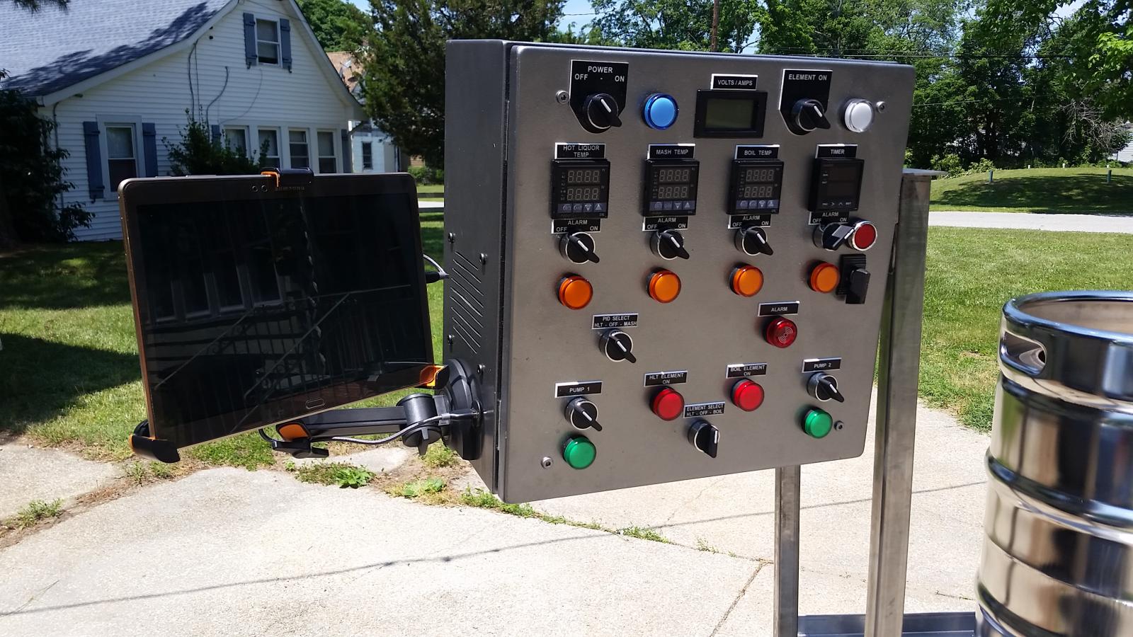
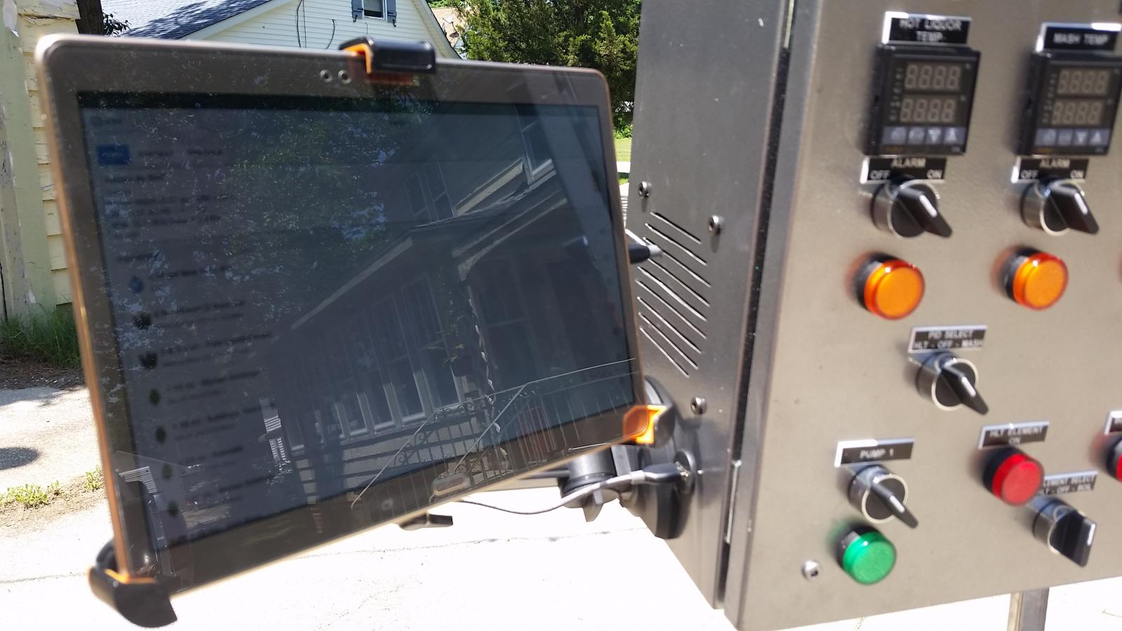
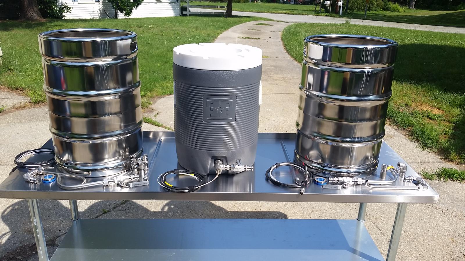
Huge E-HERMS build, 3 keggles, control panel, stir plate, ferm controller, 61 pics
- Thread starter azwillnj
- Start date

Help Support Homebrew Talk:
This site may earn a commission from merchant affiliate
links, including eBay, Amazon, and others.
wapitiscat
Well-Known Member
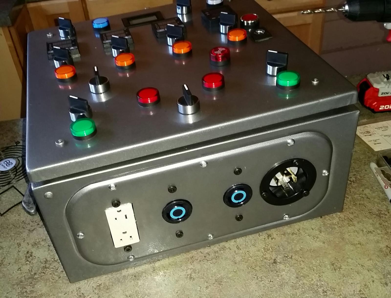
What type of control panel receptacles did you use for the heating elements?
Todd
Todd
azwillnj
Well-Known Member
What type of control panel receptacles did you use for the heating elements?
Todd
L6-30R and L6-30P
wapitiscat
Well-Known Member
L6-30R and L6-30P
Got it. L14 for the panel power supply and L6's for the heating elements.
Todd
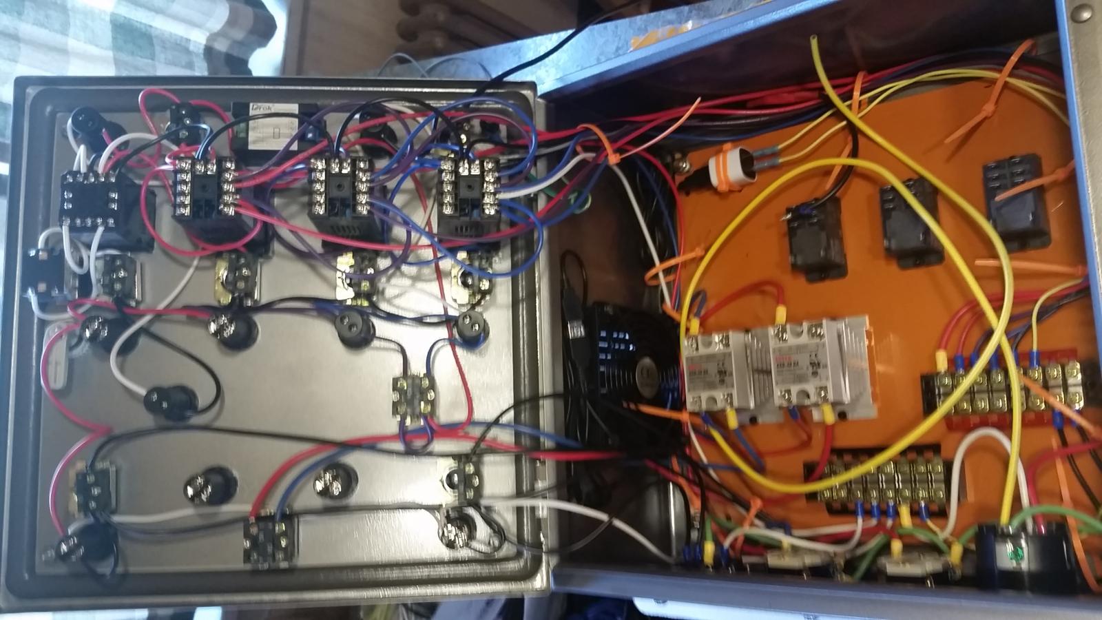
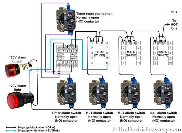
I'm following your wiring diagram but seem to have hit a mental block. From the element off-on switch to the 3 way selector switch (hlt/off/mash) it shows the lights coming from the top left & right but then it shows bridging the two wires to go to the 3 way switch for the hlt/off/boil. Wouldn't this cause both the hlt & mash lights to indicate on all of the time? Unless the switch is in the off position. 
I'M following your diagram but taking your suggestions of using the same pid controllers and I've added an auber timer.
Hopefully you are still following this thread.
I'M following your diagram but taking your suggestions of using the same pid controllers and I've added an auber timer.
Hopefully you are still following this thread.
azwillnj
Well-Known Member
I'm following your wiring diagram but seem to have hit a mental block. From the element off-on switch to the 3 way selector switch (hlt/off/mash) it shows the lights coming from the top left & right but then it shows bridging the two wires to go to the 3 way switch for the hlt/off/boil. Wouldn't this cause both the hlt & mash lights to indicate on all of the time? Unless the switch is in the off position.
I'M following your diagram but taking your suggestions of using the same pid controllers and I've added an auber timer.
Hopefully you are still following this thread.
I think you're talking about the green line that goes to the bottom 2 contactor blocks on the "PID Select Switch"? If so, here is the explanation:
In those 3-way switches all the contactor blocks are NO (normally open).
The switch has 3 positions, when the switch is in the center all the contactor blocks are disengaged, all NO in this case.
When the switch is to the left the contactors on the left are closed completing the circuit on the HLT SSR Feed and the HLT PID LED while keeping the contactors on the right side of the switch open.
When the switch is to the right the contactors on the right side are closed completing the circuit on the Mash SSR Feed and the Mash PID LED while keeping the contactors on the left side of the switch open.
In the case of the bridged LED wire, you are supplying power to both contactors simultaneously but you are only activating one at a time because of the nature of the 3-way switch.
I hope this clears it up, and I hope that was the right switch, haha.
Also, did you buy your controllers yet? Auber has a new really cool boil controller with a dial that I think would be better than the PID for controlling the boil. I just bought one to put in my new E-BIAB setup that I'm making for my small apartment. I haven't used it yet but the description of it sounds really awesome... I just wish it had a temperature display. http://www.auberins.com/index.php?main_page=product_info&cPath=53&products_id=444
Let me know if you have any other questions,
Alex.

$53.24
1pc Hose Barb/MFL 1.5" Tri Clamp to Ball Lock Post Liquid Gas Homebrew Kegging Fermentation Parts Brewer Hardware SUS304(Liquid MFL)
yunchengshiyanhuqucuichendianzishangwuyouxiangongsi

$58.16
HUIZHUGS Brewing Equipment Keg Ball Lock Faucet 30cm Reinforced Silicone Hose Secondary Fermentation Homebrew Kegging Brewing Equipment
xiangshuizhenzhanglingfengshop

$49.95 ($0.08 / Fl Oz)
$52.99 ($0.08 / Fl Oz)
Brewer's Best - 1073 - Home Brew Beer Ingredient Kit (5 gallon), (Blueberry Honey Ale) Golden
Amazon.com

$172.35
2 Inch Tri Clamp Keg Manifold With Ball Lock Posts, Pressure Gauge, PRV (0-30 PSI) – Homebrew, Fermentation, Kegging System
wuhanshijiayangzhiyimaoyiyouxiangongsi

$53.24
1pc Hose Barb/MFL 1.5" Tri Clamp to Ball Lock Post Liquid Gas Homebrew Kegging Fermentation Parts Brewer Hardware SUS304(Liquid Hose Barb)
Guangshui Weilu You Trading Co., Ltd

$39.22 ($39.22 / Count)
Brewer's Best Home Brew Beer Ingredient Kit - 5 Gallon (Mexican Cerveza)
Amazon.com

$176.97
1pc Commercial Keg Manifold 2" Tri Clamp,Ball Lock Tapping Head,Pressure Gauge/Adjustable PRV for Kegging,Fermentation Control
hanhanbaihuoxiaoshoudian

$22.00 ($623.23 / Ounce)
AMZLMPKNTW Ball Lock Sample Faucet 30cm Reinforced Silicone Hose Secondary Fermentation Homebrew Kegging joyful
无为中南商贸有限公司

$7.79 ($7.79 / Count)
Craft A Brew - LalBrew Voss™ - Kveik Ale Yeast - For Craft Lagers - Ingredients for Home Brewing - Beer Making Supplies - (1 Pack)
Craft a Brew

$10.99 ($31.16 / Ounce)
Hornindal Kveik Yeast for Homebrewing - Mead, Cider, Wine, Beer - 10g Packet - Saccharomyces Cerevisiae - Sold by Shadowhive.com
Shadowhive
azwillnj
Well-Known Member
Curious on what side bit or knock out you used for your 1/2 and 1/4 couplings in your kegs?
I used a harbor freight step bit. If I had to do it again I would buy a greenlee punch off ebay. Which I actually did do for my new E-BIAB setup.. details coming soon in another huge post, most likely in 2-3 months.
Yes that does answer a lot. Thanks for your time.I think you're talking about the green line that goes to the bottom 2 contactor blocks on the "PID Select Switch"? If so, here is the explanation:
In those 3-way switches all the contactor blocks are NO (normally open).
The switch has 3 positions, when the switch is in the center all the contactor blocks are disengaged, all NO in this case.
When the switch is to the left the contactors on the left are closed completing the circuit on the HLT SSR Feed and the HLT PID LED while keeping the contactors on the right side of the switch open.
When the switch is to the right the contactors on the right side are closed completing the circuit on the Mash SSR Feed and the Mash PID LED while keeping the contactors on the left side of the switch open.
In the case of the bridged LED wire, you are supplying power to both contactors simultaneously but you are only activating one at a time because of the nature of the 3-way switch.
I hope this clears it up, and I hope that was the right switch, haha.
Also, did you buy your controllers yet? Auber has a new really cool boil controller with a dial that I think would be better than the PID for controlling the boil. I just bought one to put in my new E-BIAB setup that I'm making for my small apartment. I haven't used it yet but the description of it sounds really awesome... I just wish it had a temperature display. http://www.auberins.com/index.php?main_page=product_info&cPath=53&products_id=444
Let me know if you have any other questions,
Alex.
Yes I already have the controllers. I have 3 of the SYL-2352 PIDs. I'm about 60-70% done with wiring the controller and almost done polishing my kegs. Still have to punch holes in the kegs and solder the fittings. I'll post some pics. Your post was definitely my inspiration. I'm not doing a keggle for my Mash Tun though. I'm using the Fermenters Favorite cooler for my Mash. I got all of my fittings from Bobby at brewhardware.com.
azwillnj
Well-Known Member
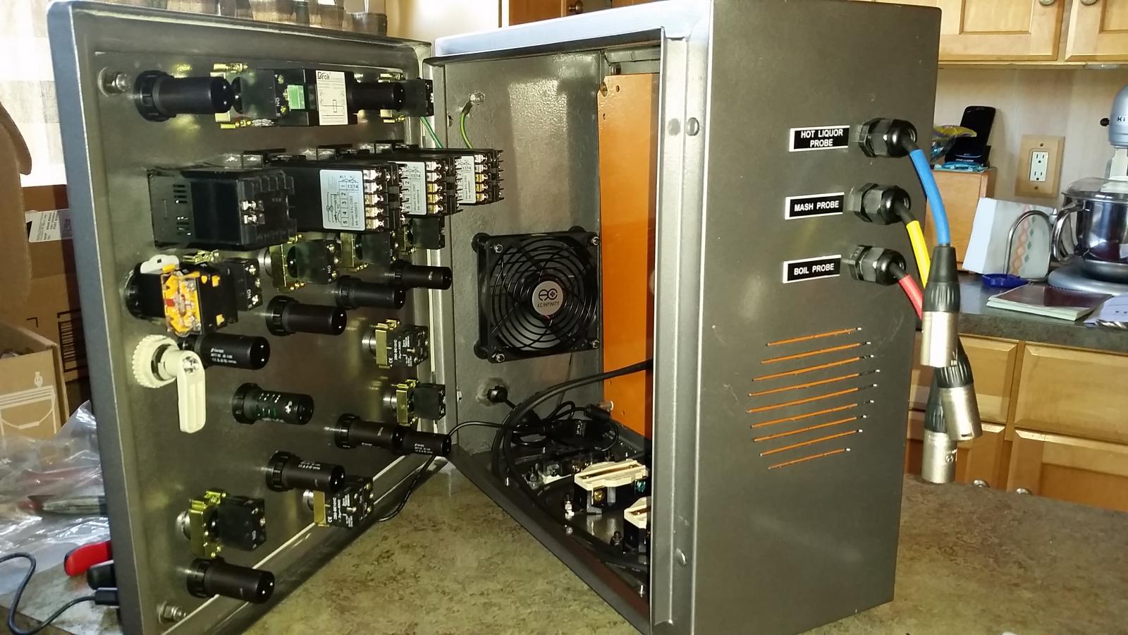
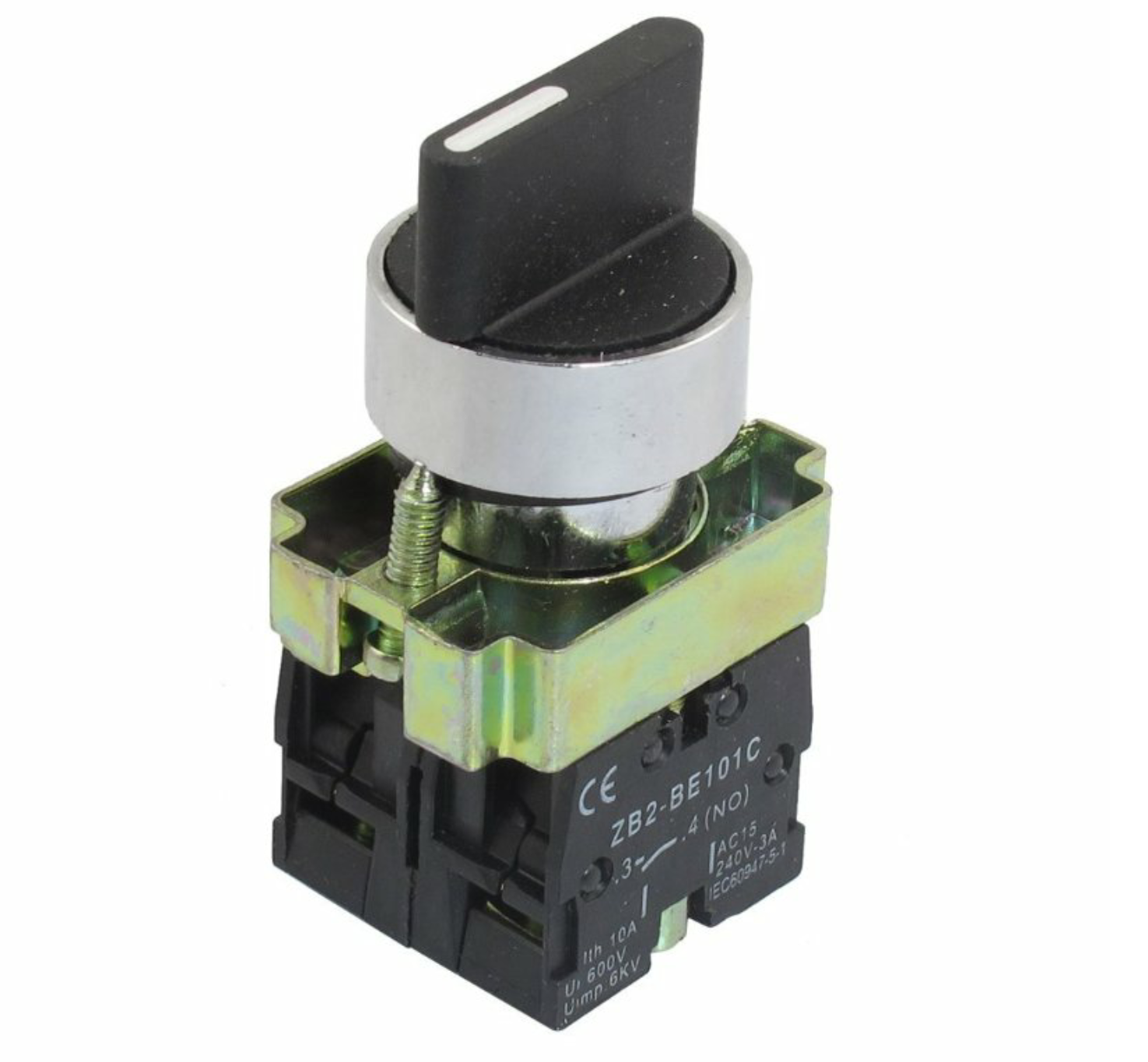
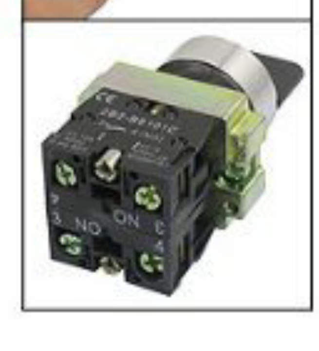
Your 3 way 2NO switches look different than mine. Mine only have 4 terminal openings but yours looks like it is stacked and has 8. Is this just a bad angle? This is the style that I have.
You can buy more contactor blocks and screw them into the bottom, the possibilities are pretty much endless.
http://www.ebay.com/itm/5pcs-TELEME...906653?hash=item5650fc68dd:g:RPUAAOxyaURTgphT
Thank you. After zooming into your photo I figured it out. I took another switch apart and realized that's what it was. I'm waiting on those parts and then I'm done the control panel. I was wondering, if I sent you a schematic of what I did with my timer, would you give it a look through just to make sure I'm good before I fire it up and fry something?You can buy more contactor blocks and screw them into the bottom, the possibilities are pretty much endless.
http://www.ebay.com/itm/5pcs-TELEME...906653?hash=item5650fc68dd:g:RPUAAOxyaURTgphT
azwillnj
Well-Known Member
Thank you. After zooming into your photo I figured it out. I took another switch apart and realized that's what it was. I'm waiting on those parts and then I'm done the control panel. I was wondering, if I sent you a schematic of what I did with my timer, would you give it a look through just to make sure I'm good before I fire it up and fry something?
Yeah, send it over, I'll take a look.
Please forgive the roughness.
I don't think 8,9,10 are right on the timer. I followed a post on electric brewery for the timer. They switched neutral on the pids. I know my light is going to light up with the alarm but I had already drilled the hole for it so I left it in.

I don't think 8,9,10 are right on the timer. I followed a post on electric brewery for the timer. They switched neutral on the pids. I know my light is going to light up with the alarm but I had already drilled the hole for it so I left it in.

azwillnj
Well-Known Member
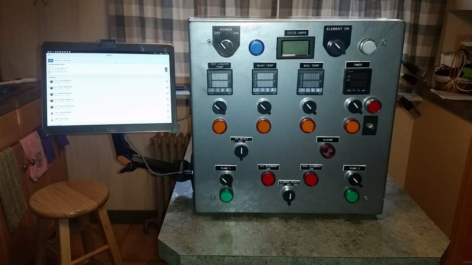
Sorry for the delay, it's been a really busy week. By the looks of the diagram you drew up you should be fine. The pictures look awesome too, i like the silver.
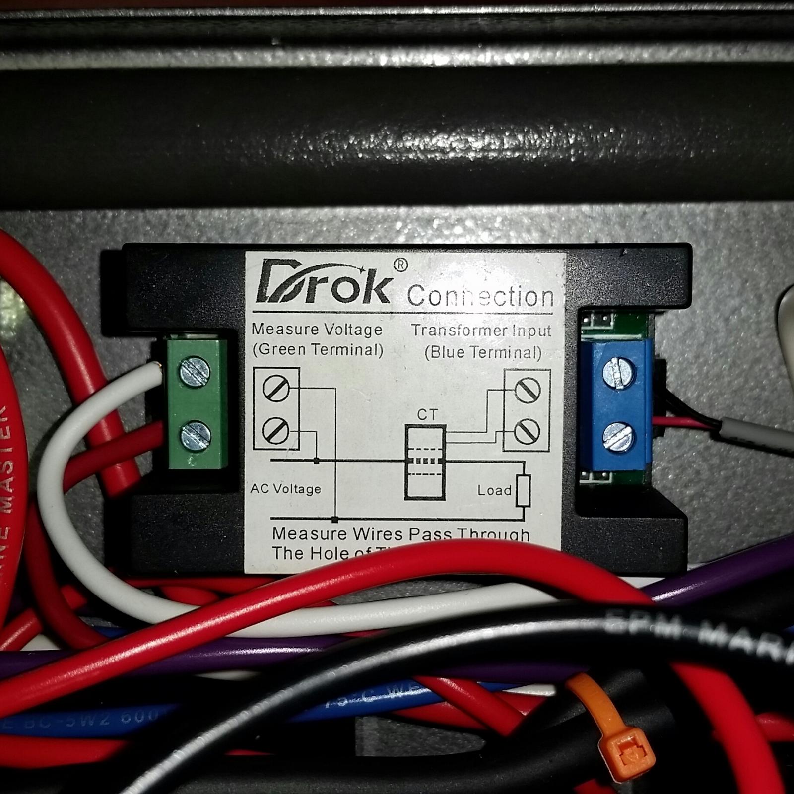
I figured it out with the meter. Your diagram shows hooking neutral and hot to the meter. My meter requires both hots to it.
I have 120v to each of my pump outlets. 240v to each element outlet. Figuring out the pids. Only have one probe ready so I have to finish the other 2.
Now on to the timer. It's not timing. Makes it a failure as a timer.

I have 120v to each of my pump outlets. 240v to each element outlet. Figuring out the pids. Only have one probe ready so I have to finish the other 2.
Now on to the timer. It's not timing. Makes it a failure as a timer.

Dfitz
Well-Known Member
Nice! I have one similar except a 20 gal. HERMS and my panel is 50amp w/an alternate system for another hobby I enjoy. No CFC?
You chilling via HERMS coil?
You chilling via HERMS coil?
Dfitz
Well-Known Member
Do you have photos?
I do but my goodies aren't as polished.
Somewhat in disarray as school is letting out here and I have kids helping me clean out my garage.
Panel serves two functions, one for brewing and the other not open for discussion.
My boil keg, as you can see by the bottom in the spirit of things I did attempt to polish a bit. No thanks! lol
Then there's my old crawfish pot HERMS, I had it on hand so its what I'll be using for a while. 40' of 1/2 tubing was a bear to roll to fit but it's expandable and really works well managing a mash temp. on a 25 gallon pot. (not shown). I hear people talk about recirculating their HERMS but I haven't noticed any issues.
I picked up a Pico false bottom for my mash tun. I think it'll work well.
Like I say, no bling and cleaning the garage so it'll be out of commission for a couple weeks while I re-organize and make more room. I have a fast ferment conical in a controlled freezer, stir plate ect. I really need to organize to fit another freezer.
I do need to clean things up a bit when I get them situated into a fitting position but I can probably assure you no polishing is in my plans. That's a young man's pleasure!
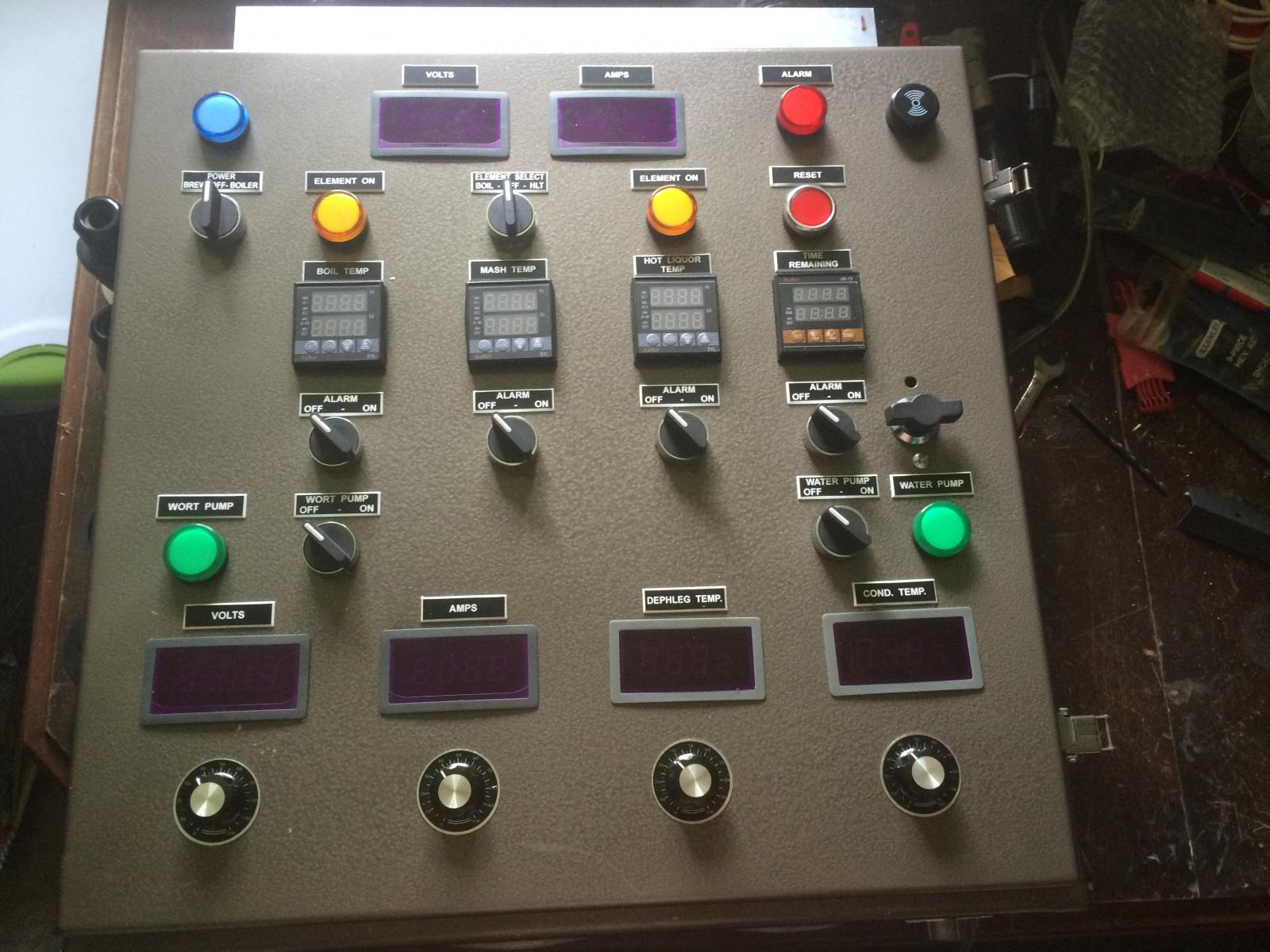
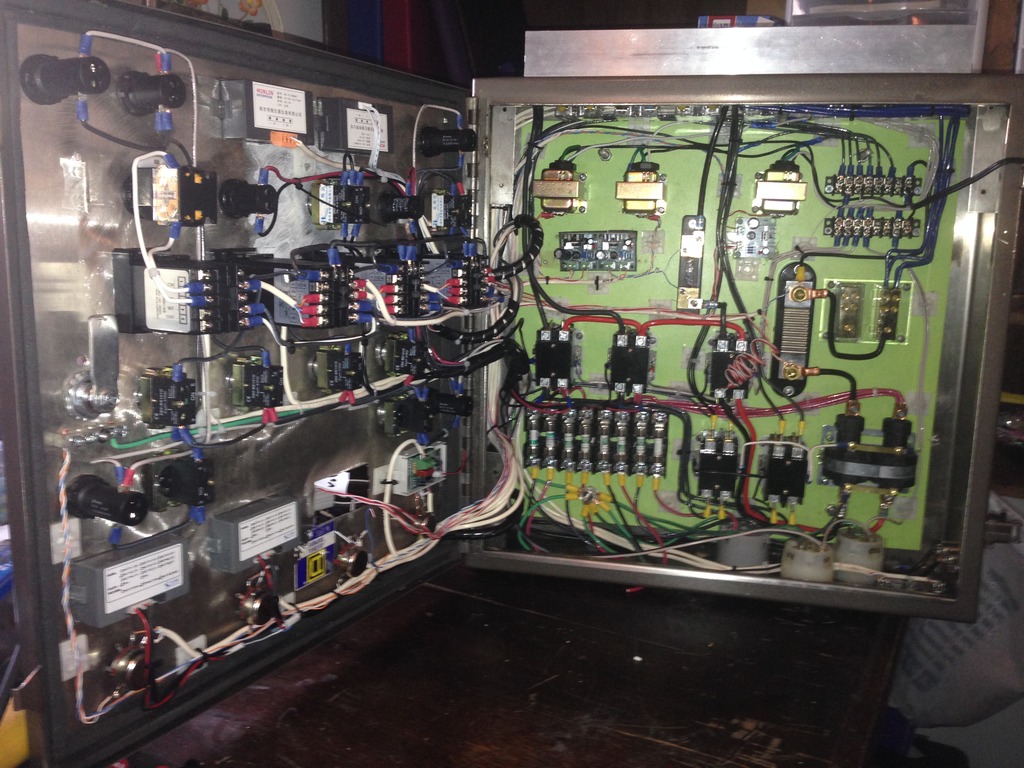
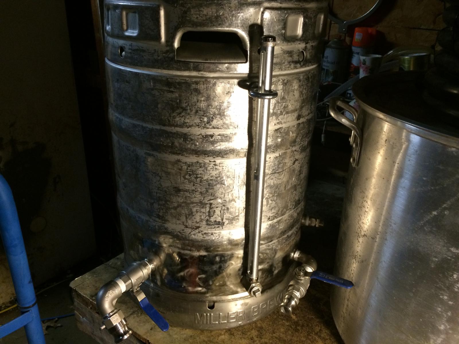
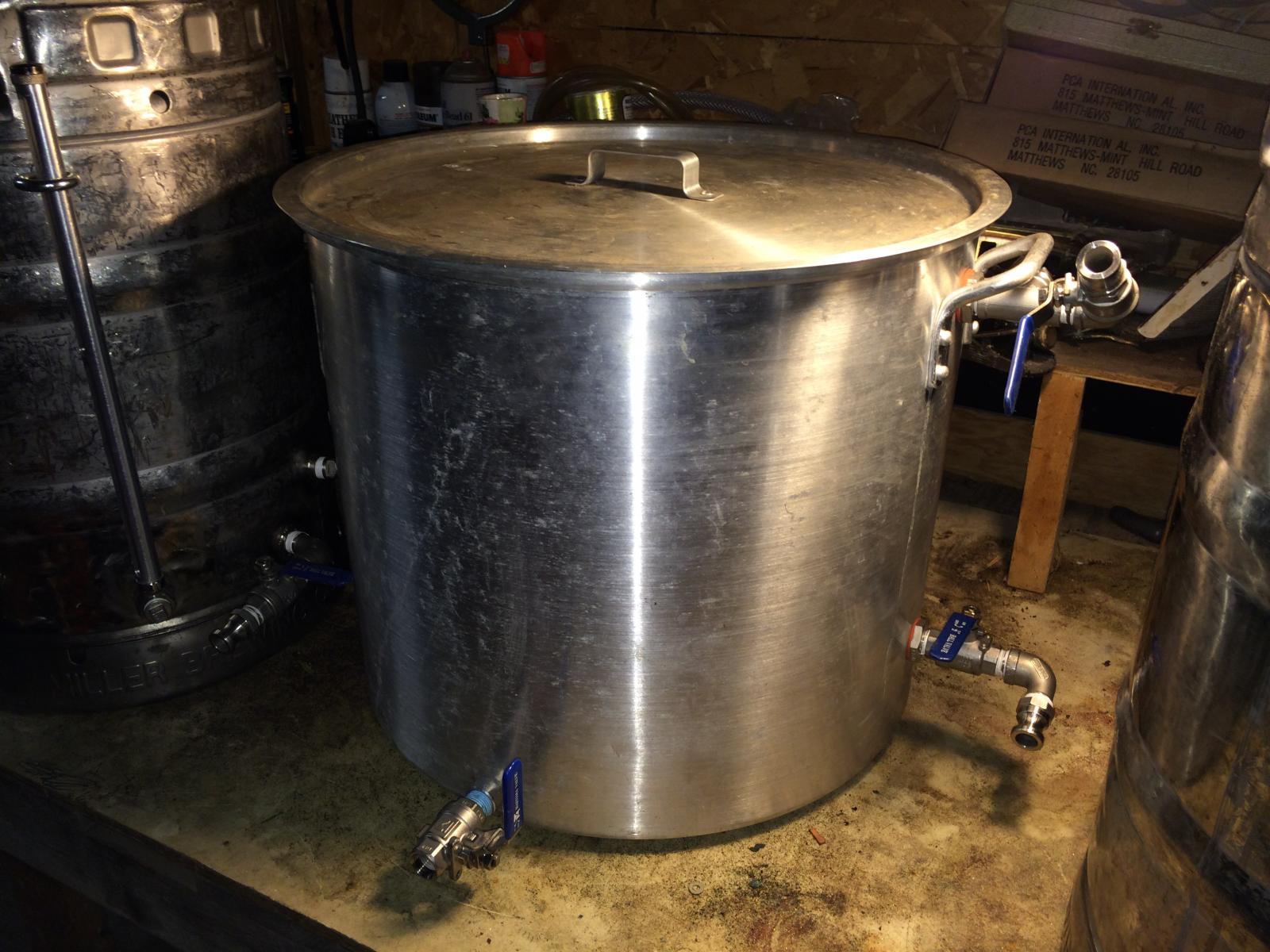
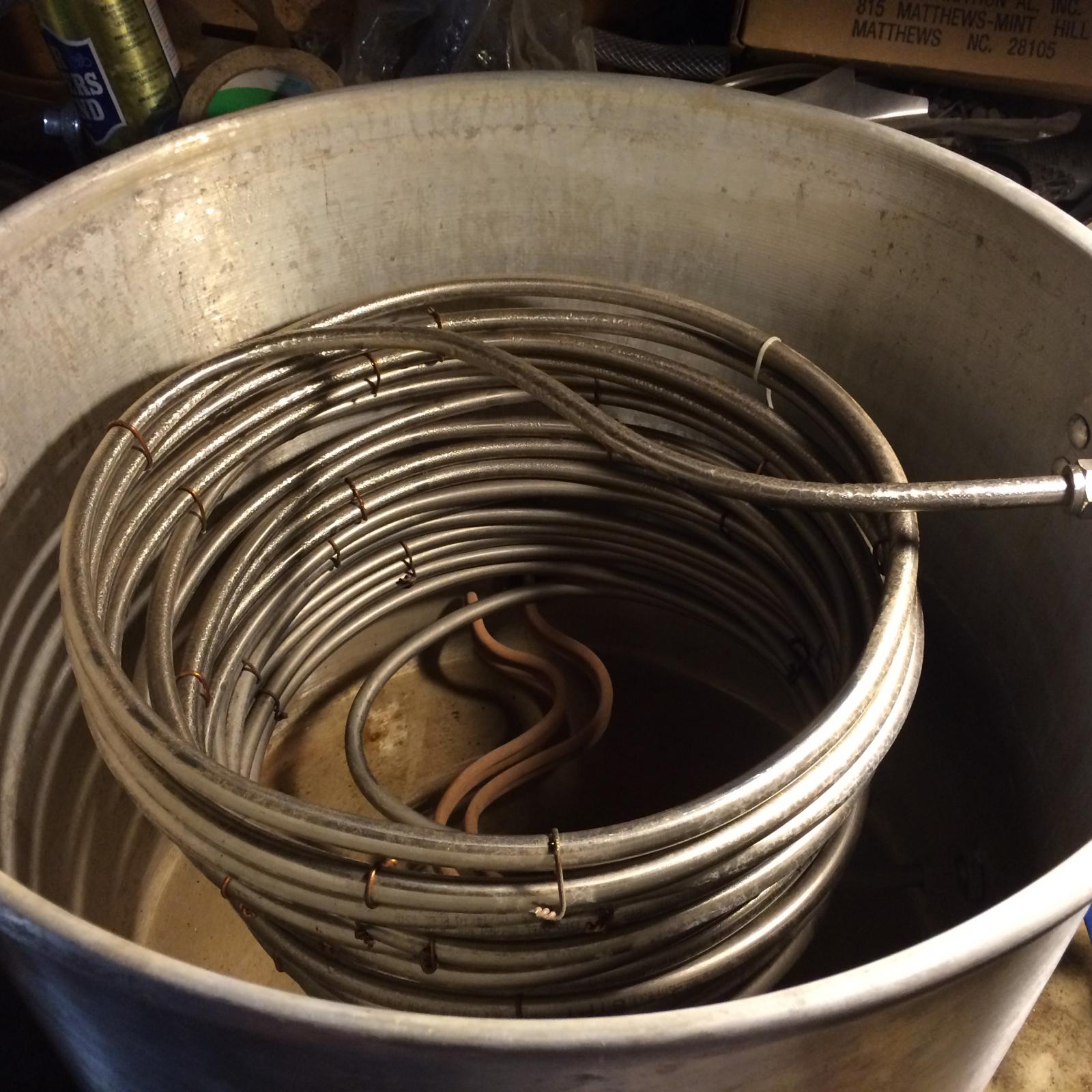


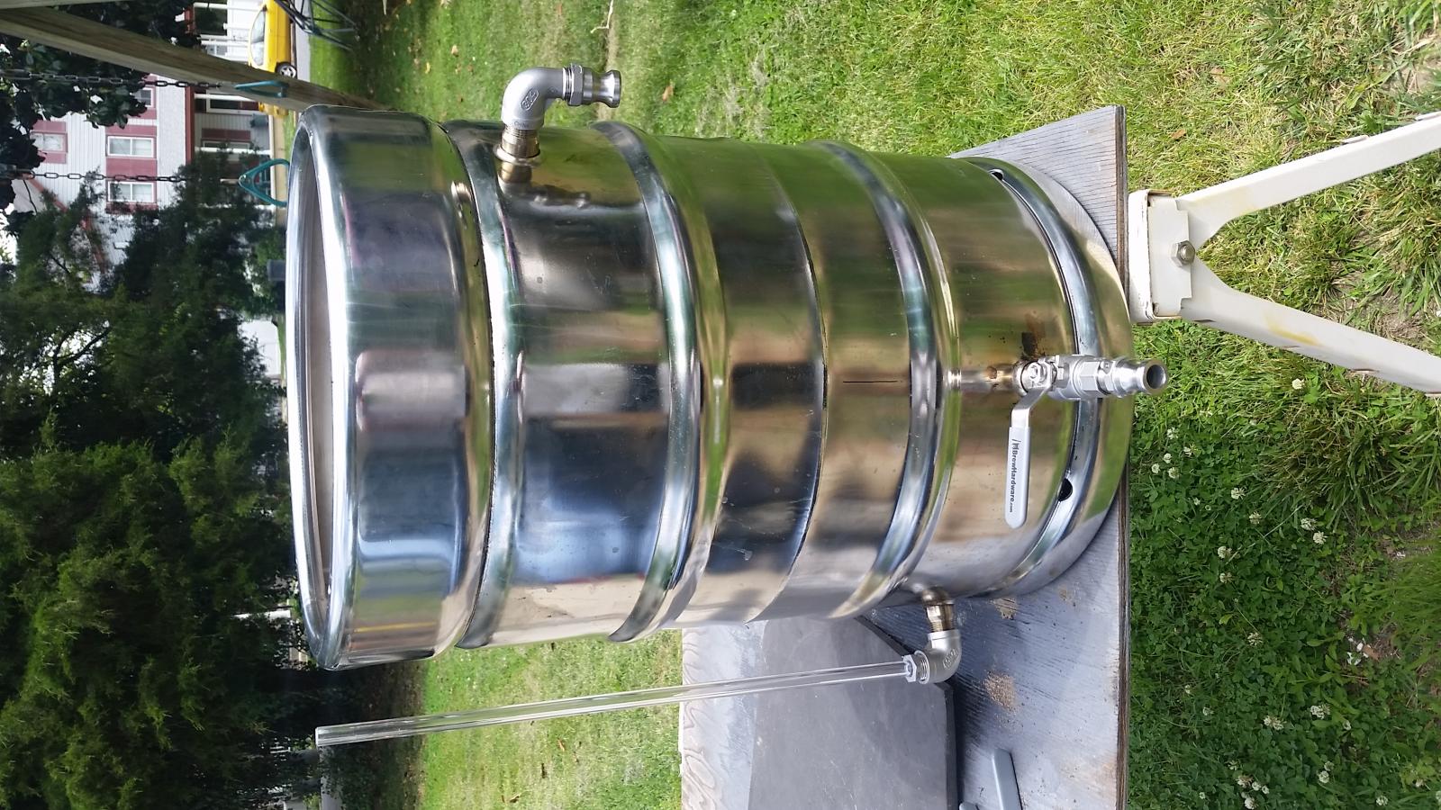
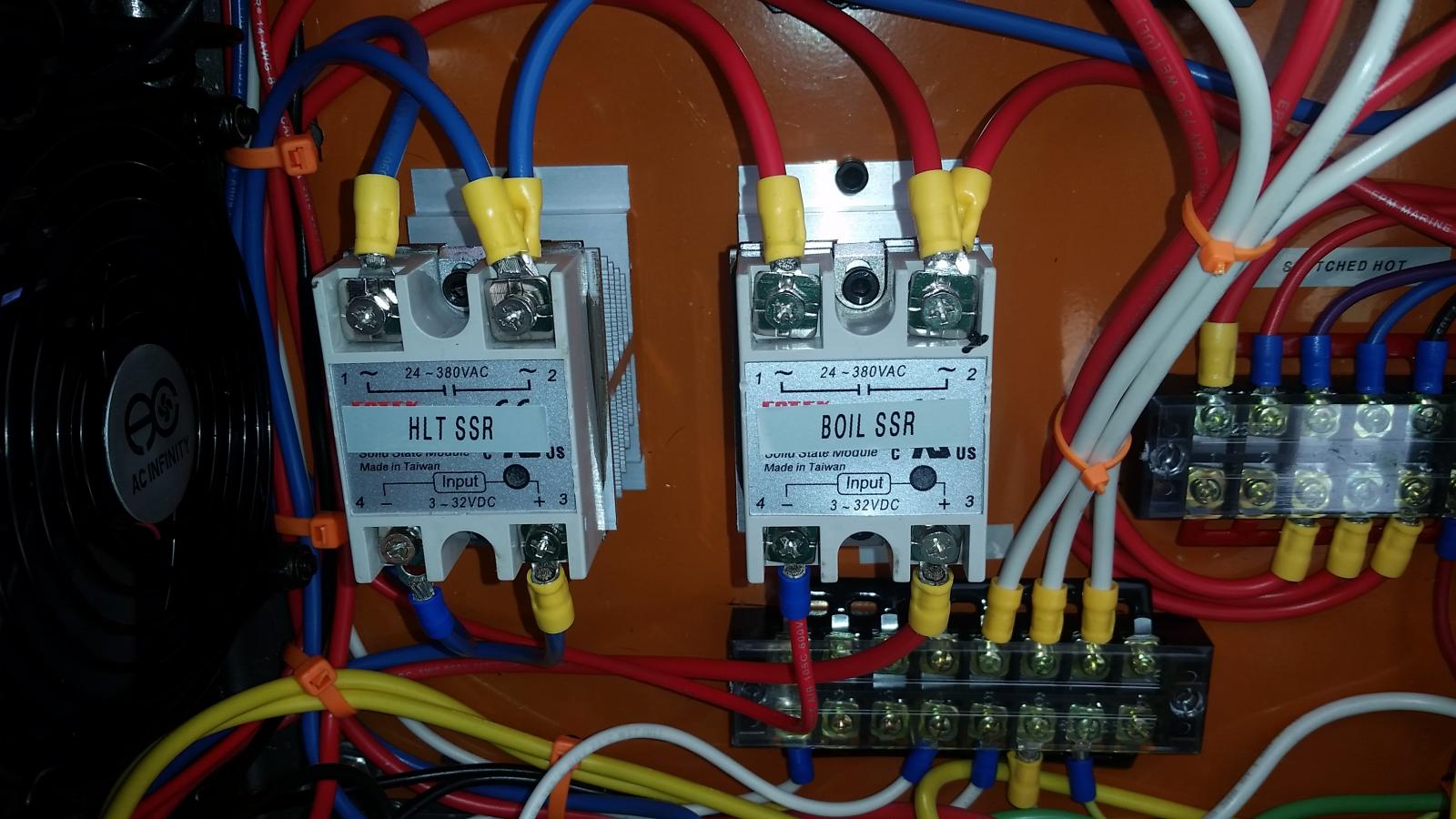
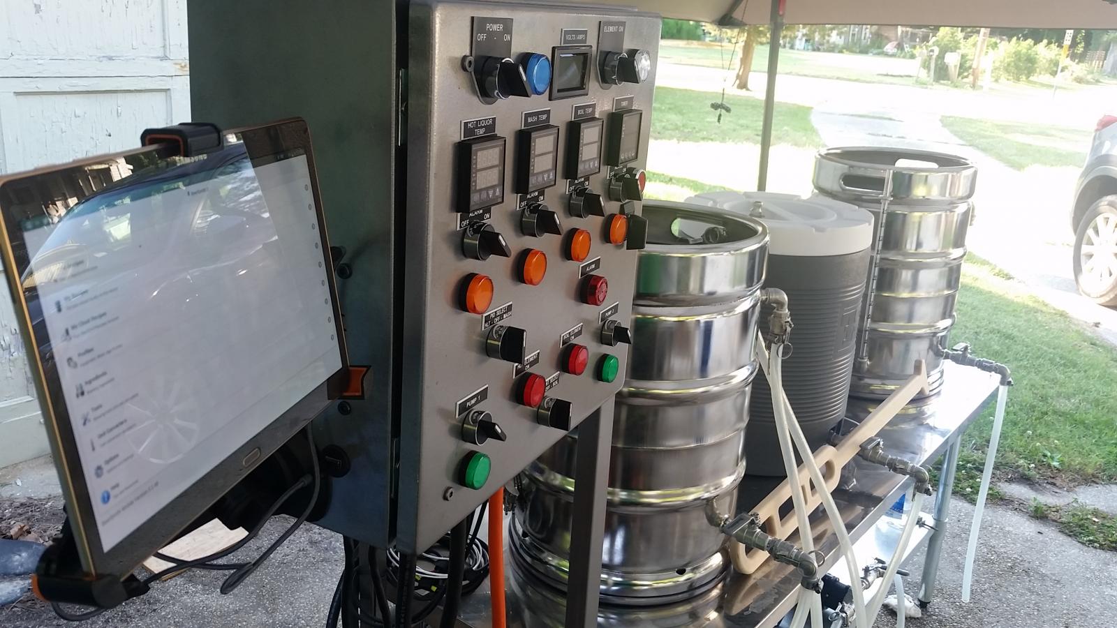
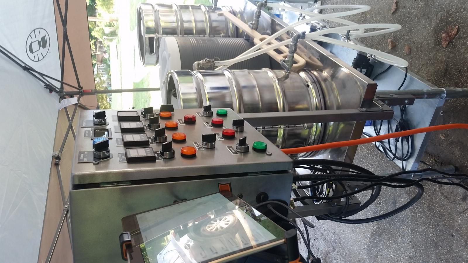
I decided to polish because of the original poster's (azwillnj) pictures. It's easy to clean too. I'm more middle aged and hated every minute of polishing, but my obsessive side took over. I'm glad I did. Did you build that panel? Very clean wiring job. I attempted to keep mine that organized but slowly lost control over tidiness. It's still way cleaner than others I've seen examples of though. I still have to trace the root of my problem with blowing the main breaker when I turn on my boil element. Gonna do some trouble shooting today.
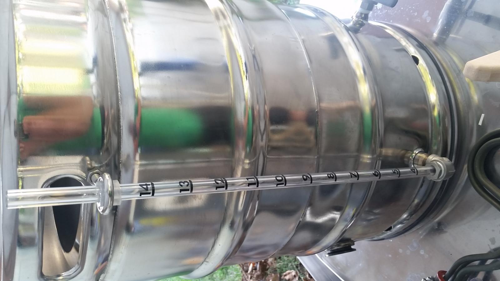
So I found my problem. One of my ssr relays went bad. It doesn't make sense since I only fired it up to verify that everything worked prior to hooking up elements. It worked then but now it doesn't. So I ordered another and a back up. Hopefully that's it for replacing brand new stuff. Calibrated my sight glasses today too.



Similar threads
- Replies
- 0
- Views
- 255
- Replies
- 1
- Views
- 998
- Replies
- 10
- Views
- 3K


![Craft A Brew - Safale BE-256 Yeast - Fermentis - Belgian Ale Dry Yeast - For Belgian & Strong Ales - Ingredients for Home Brewing - Beer Making Supplies - [3 Pack]](https://m.media-amazon.com/images/I/51bcKEwQmWL._SL500_.jpg)

