HOWTO - Make a BrewPi Fermentation Controller For Cheap

Homebrew Talk - Beer, Wine, Mead, & Cider Brewing Discussion Forum

Help Support Homebrew Talk - Beer, Wine, Mead, & Cider Brewing Discussion Forum:

This site may earn a commission from merchant affiliate links, including eBay, Amazon, and others.
Status
Not open for further replies.
The Chamber fan runs when either the Heat or Cool mode is enabled.

I run three chambers and my keezer on BrewPi and don't use the Chamber Fan function on any of them, as imo it's sub-optimal compared to simply running the fans 24/7...

Cheers!

[edit] Can't really say if your approach is the soundest. I do know both of my frost-free top-freezer fridges have evap fans and one of them has a condenser fan as well. Rather than trying to beat that game I simply control both from their line cords.

Sometimes one decides to interrupt a cooling cycle with a defrost cycle.
NBD, there'll be a blip in the corresponding BrewPi chart but things return to normal in short order...
 
Thank you Day_trippr.

Indeed, the problem is that there are two independent systems:
the combi board and the defrost system and on the other hand brewpi.

So, if "chamber fan" acts only when the relay of cold or heat is activated, it is not enough for my system. Today I observed that for 1.5h the compressor has been connected but the temperature did not decrease when the fan does not work. this is unaceptable :(

One idea I had is to disconnect the defrost resistor ... but I do not want to run the risk of spoiling or breaking the fridge for it.

Another one that I think may be the most accurate is to have the fan control of the combi itself with a third relay: this would always be on less when the brewpi heat relay is activated. This optimizes the system.

What do you think about it?
TY again
 
I gather the fan in question is for the evaporator, and if so it makes sense that fan doesn't run when the defrost heater is on, to prevent unnecessarily warming the entire cabinet interior. By controlling the compressor independently of whatever quasi-brain controls the rest of the unit you've decoupled the compressor from the defrost controller.

Perhaps it would make more sense to have the defrost state inhibit the compressor?
Which would pretty much mean reconnecting everything as stock and running the unit from its line cord...

Cheers!
 
Thanks again.

What you indicate in my opinion is the best solution ... but complicated for my near nul knowledge of electronics.
Ideally, when electrical voltage is detected in the defrost resistor, it will cancel both the fan (this is done by the fridge plate) and the electrical supply of the compressor, but I do not know how to do it ... I also think it would involve pulling out the cable of high voltage from this resistance of defrost to the outside ... and I do not want to drill, nor to remove it by the evaporator since there can be humidity.
The temperature probes are now drained through the bottom hole of the evaporator.

It would be an interesting topic to address, as I think several recent comments in this forum report these problems.

Another alternative solution I am thinking about could be done with the same "heater" arduino relay:
-Drill the base between freezer and refrigerator. I have confirmed with the manufacturer that there is no problem, that there is only one insulation without tubes or cables.
- Place a low voltage fan (from a PC for example) and feed it externally with a 12V transformer, connecting it to the "NO" (normally open) relay output. So this fan would always be ON except when brewpi activates this "heat" relay briefly to warm up. The normally closed NC relay output could cut off the fan power.

Problems: we also have to externally feed the defrost fan with an electric wire from the outside, although it would be low voltage. However, the heat of defrost resistance would no longer rise. The advantage I see of this tune is that there is a plastic separation between the evaporator and the freezing chamber, and even though defrost resistance is activated, even if the new fan is running, it would not raise heat.

Any suggestions or ideas better?

Will this be a hacking level 4 :)

Cheers!

PS:Manufacturer's response (Teka): You can make the refrigerator plate always ask for cold in the following way: if we extract the 2 temperature probes and measure them at room temperature with an ohmmeter, we can bypass them with a resistance of this value Probe connectors and remove these.

As soon as I finish an IPA fermentation I will investigate this matter :)
 
Last edited:
Assuming the defrost heater is a 110vac device, you could use that circuit to energize a relay (with a 110vac coil). The compressor AC would be routed through the NC points. Thus, when the relay is energized by an active defrost heater, it would prevent the compressor from turning on.

But, again, that starts looking remarkably like the oem functionality, controlled via the line cord.

I'd have to actually study your "Level 4" concept, but right now there's drinking to be done :mug:

Cheers!
 
I'm sorry for my poor understanding in English ... :confused:

By the way: which means exactly when you say "controlled via the line cord" or "reconnecting everything as a stock and running the unit from its line cord ..." ??? Can you detail it better?

TY :tank:
Cheers!
 
I'm sorry for my poor understanding in English ... :confused:

By the way: which means exactly when you say "controlled via the line cord" or "reconnecting everything as a stock and running the unit from its line cord ..." ??? Can you detail it better?

TY :tank:
Cheers!

Basically, do not modify anything, and control the fridge by turning the power on and off via its power supply cord.
 
What he said^.

If you look at the wiring diagram on the first post of this massive thread, it is for the BrewPi to control a standard electrical outlet, with one receptacle of the outlet controlling the refrigerator or freezer, and the other receptacle controlling a heating source. day_trippr is suggesting that you'll get the functionality you're after by simply leaving your unit in tact and plugging it into the outlet. The freezer's defrost cycle may momentarily turn off the cooling function of the unit, but that will be only for a short while and it won't affect the performance of your BrewPi noticeably.

As far as having a fan, we have found that it is best to have a fan running inside of your unit full time, even when the unit is heating. Don't think of the fan as a cooling component, think of it for moving air in the unit and stabilizing temperatures top to bottom and side to side to improve the performance overall.

I have two units running, one with a fan and one without (I'm waiting on a shield build in order to add the power for the fan). The one with the fan is within 0.15 deg F warm or cold at any given time. It is hella (very) stable. The one without the fan is generally within 1 deg F warm or cold. Still acceptable, but the 2 degree swing is easily fixed with a cheap fan.

Hope this helps.
 
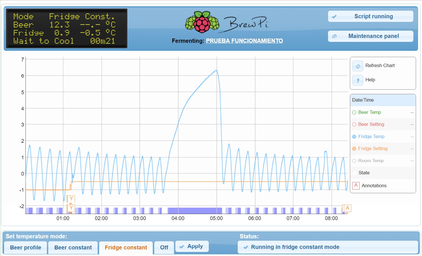
I have been evaluating the different options at a practical level and I think that, as you say, the best option is to put an external fan to raise the cold from the freezer 24/7. Thus we avoid absurd situations: 2h running defrost heater, evaporator fan stopped and compressor constantly connected by brewpi ... which in turn causes the defrost heater not to disconnect (see img attached as example of coldcrash in freezer) :(

In this way, with the external fan between the 2 chambers and only doing this, does not interfere in the internal operation of defrost. The cold demand of the probe from the upper chamber would stop when the temperature reached quickly and this will cause brewpi to disconnect the compressor.

So we will keep a level 3 of hacking.... and good beer without headaches :D

I hope this debate has been able to help in addition all the doubts about fluctuations in brewpi graphs.

Thanks for the comments and help

img coldcrash.jpg
 
Last edited:
Hi all, a question:
I have checked a temperature difference around 1°C or higher in the probes connected to Brewpi+arduino (legacy).

So, is there any way to calibrate them and enter the temperature calibration parameters in Brewpi?

Thanks :tank:
 
Thanks both!
WOW....what a nice work

Will try and comment...but not now: Saison recipe is waiting :D
Cheers!! :mug:
 
Incoming british noob alert... :confused:

My overly excited self bought all I (thought was) needed to start this project...
I have finally come to the assembly and have hit a silly snag... my dual relay board does not look like the ones in the schematics diagram...
It's certainly similar, but in terms of putting the wires where they are supposed to go I'm left a little dumbfounded.
Have I bought the wrong thing or I am I being a little silly?
In the top left I can see GND which I'm looking to attach the ground to, but then next to that is "VIN" which I'm assuming is the "Voltage IN" is in place of the "VCC". So that leaves me unsure what to do with the other two wires?

Any help would be greatly appreciated! :mug:

IMG_4185.jpg


FullSizeRender.jpg
 
Looking at what I can find regarding that dual-relay shield, if you plug it atop the Uno, you'll pretty much have all you need to run the Cool and Heat relays. It will pick up +5V and GND from the Uno and make control connections to the relay pick circuits. Then you can attach your One-Wire probes to analog pin A4.

On that note, per the schematic for that shield, the one thing to keep in mind is one of the relays will respond to digital IO 4 and the other to digital IO 5.

That might be considered a tad non-standard - the optimal IO assignment puts the cool and heat functions on digital IO 5 & 6, respectively - and it'll mean not being able to exploit the Door function which is "normally" associated with digital IO 4 and can't be controlled by either digital IO 5 or 6. But I'm guessing most people don't implement that to begin with...

Cheers!
 
Ahhhh I see! That makes so much sense. Thanks day_trippr!
I'll have a little play around with it tonight. Hopefully it should be fairly straight forward now. ...saying that, I'll probably be back on here with another silly question in a few days!
Cheers!
 
I purchased the Raspberry Pi 3, the Arduino UNO R3 ATmega328P and the rest of the parts and built by control box. I was able to install the OS on the microSD and am able to see the brewpi page in my laptop browser. However, the main page has the message "Could not receive version from the controller Please (re)program your control." I went to the maintenance panel and attempted to program the controller. Now I have two problems. First, I'm asked to provide a path to a hex file, but I have no idea where to get that file. Note the "docs.brewpi.com" is no longer responding. Also, when I did hit the program button, it seems that the raspberry pi failed to get a serial connection with the controller. So, I'm kinda stuck now. Any help would be appreciated.

OK, it looks like I figured out the problem and everything is working now. However, I'm a bit clueless on actually using the brewpi web interface. Is there a user's manual for operating the software? When I google for brewpi manual, it seems that I only get pages for setting up the system and installing s/w, not anything on the operation of the software after everything is set up. One of my first tasks is to check to see if the rest of the h/w is setup correctly, e.g., the solenoids engage properly when brewpi needs to engage the fridge or the heater. I'd prefer to do that before hooking up hot power.
 
For the latest Arduino BrewPi hex file, go to this page and download by clicking on the brewpi-arduino-uno-revC-0_2_10.hex link.
When you go to flash your Uno via the BrewPi gui, point to the downloaded file...

Cheers!
 
My BrewPi now seems to be working. Where can I find information on using it, like a user's manual or thorough on-line demo? The docs.brewpi.com site seems to have been taken down.
 
My BrewPi now seems to be working. Where can I find information on using it, like a user's manual or thorough on-line demo? The docs.brewpi.com site seems to have been taken down.


All that is secret… if you wish to proceed you just prove you are worthy…
 
All that is secret… if you wish to proceed you just prove you are worthy…

I found the docs on github. I downloaded and installed python, pip, and sphinx. I set the path and SPHINXBUILD environment variables. However, whenever I try to compile the documentation into html, I keep getting an error message that the SPHINXBUILD variable needs to be set. Any idea what I'm doing wrong? I running in Windows 10.
 
I'm pretty sure wbarber69 is kidding... It would probably be easier if you just asked your questions here. Lot's of long time, knowledgeable users in this thread. (wbarber69 being one of them) What kind of information are you looking for?
 
I understand that wbarber69 was kidding. Still the basic info I'm trying to find is some type of user's manual for the brewpi. I think I have it up and running, but need to run some tests (that would engage the power to the chiller and warmer) before using actual power. Then the basic usage of the tool. As I posted above, I did see source for building a http manual using python, etc., but now I'm getting into some Windows tech issues.
 
If a user's manual is what you seek, I won't dissuade you any further. If you have luck, please post your findings here. If you strike out, come back and ask questions.
 
WARNING: Python geek speak! This is for people building the html user's manual for BrewPi from the github repository. I solved one problem, but I seem to have run into another. Compiling the manual to html requires running a python tool (sphinx) against the repository files. I had one problem when I installed python and its tools in the public "Program Files (x86)" directory. The instructions for building the manual say to define an environment variable for the sphinx tool, which in my case was "c:\Program Files (x86)\Python36-32\Scripts\sphinx-build.exe"
The problem I just solved is that the parentheses and spaces were causing problems with how the make.bat file was using the environment variable. I solved that problem by using the microsoft escape character '^' before the spaces and parenthesis characters in the environment variable definition. However, now when I try to create the html by issuing the "make.bat html" command, I get an error that sphinx can't file the "Files" subdirectory. I don't see where a Files subdirectory is referenced in the bat file, so sphinx must be assuming somehow. Any of you python/sphinx experts have a clue what's going on?
 
First attempt building the Brewpi using the brewpi wiki and all parts recommended.

Have an RPI running Jesse and I went through the installation process and it recognizes both the two sensors and the 2 channel relay. I have not tested out the actual power to the outlets yet because I am having issues with the "script running" portion.

Currently the process is going back and forth between running and not running intermittently. About 5 seconds of each back and forth.

Not sure what logs are needed to help trouble shoot this or pictures but please let me know and I will provide them.

Thanks,
Jeff
 
Typically, that's the result of powering the Uno via its USB connection over a marginal cable, or using an RPi power supply not up to the task...

Cheers!
 
First attempt building the Brewpi using the brewpi wiki and all parts recommended.

Have an RPI running Jesse and I went through the installation process and it recognizes both the two sensors and the 2 channel relay. I have not tested out the actual power to the outlets yet because I am having issues with the "script running" portion.

Currently the process is going back and forth between running and not running intermittently. About 5 seconds of each back and forth.

Not sure what logs are needed to help trouble shoot this or pictures but please let me know and I will provide them.

Thanks,
Jeff


Don't use safari…
 
WARNING: Python geek speak! This is for people building the html user's manual for BrewPi from the github repository. I solved one problem, but I seem to have run into another. Compiling the manual to html requires running a python tool (sphinx) against the repository files. I had one problem when I installed python and its tools in the public "Program Files (x86)" directory. The instructions for building the manual say to define an environment variable for the sphinx tool, which in my case was "c:\Program Files (x86)\Python36-32\Scripts\sphinx-build.exe"
The problem I just solved is that the parentheses and spaces were causing problems with how the make.bat file was using the environment variable. I solved that problem by using the microsoft escape character '^' before the spaces and parenthesis characters in the environment variable definition. However, now when I try to create the html by issuing the "make.bat html" command, I get an error that sphinx can't file the "Files" subdirectory. I don't see where a Files subdirectory is referenced in the bat file, so sphinx must be assuming somehow. Any of you python/sphinx experts have a clue what's going on?

Wild guess - try to escape the "space" in Program Files as well....

regs,

peram
 
Last edited:
wbarber69 and day_trippr,

Thanks for the advice was using safari (switched to Chrome) and got a better usb cable for Arduino and now it seems to be running fine. Already had a wall plug for my RPI.

Outlet tested fine so now time to start testing it with fridge, heater and a brewbucket.

Thanks for the great support and setup information as everyone on this thread helping everyone else definitely helped me.

Will probably be back with more issues or fine tuning the process of Brewpi itself. Plan on adding a second one in the future once I get the one running fine.

V/R,
Jeff
 
Still trying to learn how to use my brewpi. One thing I note is that the power plugs being controlled by the unit are connected to the 'normally on' connectors of the relay switch. Both relays are engaged, which means, the plugs would not be getting power if the unit was connected to power. This is confirmed in that both input signals to the relays are at 5v. Does this mean that if the brewpi should lose power, would both the heater and chiller be engaged? I'm not sure that's the best design.
WRT the software, I have some questions on the web display. For example, the top graph lines have boxes with letters on them. So far I see G, F, and I. What do these mean? I note the legend to the right has a reference to 'state', but I can't seem to get the state to display. How can I make that happen? Lastly, according to my test profile, the chiller should be engaged, but that doesn't seem to be happening. The bottom chart shows my test profile and the status indicates "Running beer profile test", so I think the profile should be active. Thoughts?

Do you mean "normally on" or "N/O" (or "N/C")?

What relays are you using? Many of the common relay modules are active low, which means that a 5V signal would cause the relay to not be energised. If your relays are energised when 5V is present then you need to invert the output signals.

The little boxes with letters in them are annotations. They show that some event happened at that time. Hover the mouse over them to see the note of the event.
 
Still trying to learn how to use my brewpi. One thing I note is that the power plugs being controlled by the unit are connected to the 'normally on' connectors of the relay switch.

"NO" is "Normally Open" - not "Normally On".
"NC" is "Normally Closed".

The Cool and Heat AC switched AC feeds should be routed through the "NO" contacts - and the actuators set for "Inverted" in the Device Configuration panel.

As for the rest:

- The boxes (Annotations) indicate when you made some change to the controller (like, changed the temperature).

- State is always displayed (that's the bottom-most plot that shows when either Cool or Heat actuators are active).

- My guess is you have the relays wired wrong and haven't set the Inverted state for the actuators...

Cheers!
 
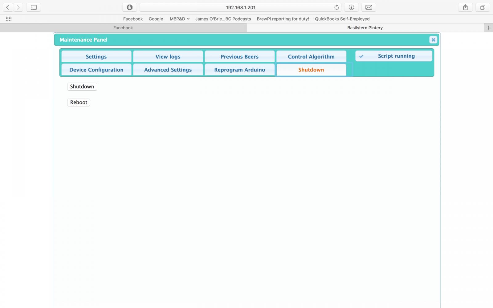
I got tired of having to log into my computer, open terminal, ssh into the brewpi, and then run a command to power it down. So I did something about it! I made an extra option on the maintenance panel to shutdown and reboot the system. I also am wiring up a switch so I can turn it off (or on) with a much of a physical button on the brewpi housing.

I know it is fairly cheap to run a brewpi 24/365, but I still like to unplug it when I'm not using, or when we get a lightning storm coming through. If anyone is interested, I can try to put together a tutorial on how to do it.

EDIT: Tutorial is here, and just a few posts down from here.

Screen Shot 2017-05-09 at 12.21.41 PM.jpg
 
I got tired of having to log into my computer, open terminal, ssh into the brewpi, and then run a command to power it down. So I did something about it! I made an extra option on the maintenance panel to shutdown and reboot the system. I also am wiring up a switch so I can turn it off (or on) with a much of a physical button on the brewpi housing.

I know it is fairly cheap to run a brewpi 24/365, but I still like to unplug it when I'm not using, or when we get a lightning storm coming through. If anyone is interested, I can try to put together a tutorial on how to do it.
I'm interested in a tutorial.
 
I got tired of having to log into my computer, open terminal, ssh into the brewpi, and then run a command to power it down. So I did something about it! I made an extra option on the maintenance panel to shutdown and reboot the system. I also am wiring up a switch so I can turn it off (or on) with a much of a physical button on the brewpi housing.

I know it is fairly cheap to run a brewpi 24/365, but I still like to unplug it when I'm not using, or when we get a lightning storm coming through. If anyone is interested, I can try to put together a tutorial on how to do it.

Interested too. Post it up.
 
I got tired of having to log into my computer, open terminal, ssh into the brewpi, and then run a command to power it down. So I did something about it! I made an extra option on the maintenance panel to shutdown and reboot the system. I also am wiring up a switch so I can turn it off (or on) with a much of a physical button on the brewpi housing.

I know it is fairly cheap to run a brewpi 24/365, but I still like to unplug it when I'm not using, or when we get a lightning storm coming through. If anyone is interested, I can try to put together a tutorial on how to do it.


Saw this the other day, seems like a pretty cool hack…
https://youtu.be/A08IrJ3ECuA
 
Saw this the other day, seems like a pretty cool hack…

https://youtu.be/A08IrJ3ECuA
Ghostery prevented a redirect from
go.skimresources.com to go.redirectingat.com,
which is part of SkimLinks.

This tag appears to redirect to
http://go.redirectingat.com/?id=824...om/search.php?searchid=37633641&xtz=420&abp=1
If this link doesn't look right and you'd like to proceed, click on the icon below to allow SkimLinks and reload.
Allow tags once until final destination is reached. Always allow and reload.
 
Shutdown/Reboot HTML Buttons
DISCLAIMER: I am not responsible for the loss of life, limb, Raspberry Pi, or the love of your family. Proceed at your own risk. Back up your stuff, yada, yada, yada.

1. Give www-data access to run the commands
First off, we need to give the webpage (www-data) access to run the shutdown and reboot commands.

From the command line type
Code:
sudo visudo

Scroll down until you see this:
Code:
#includedir /etc/sudoers.d
pi ALL=(ALL) NOPASSWD: ALL

Directly below that type in
Code:
www-data ALL=NOPASSWD: /sbin/reboot, /sbin/shutdown

Press Ctrl-X to save, Y to confirm, and then Enter to confirm the file name

2. Create the PHP pages that will be run by the buttons
I did this step through the GUI, but I suppose you can do it through the command line as well.

Navigate to /var/www/ (if you're running Jessie, it might be /var/www/html)

Create a new empty file, name it reboot.php, and inside it type the following
PHP:
<?php system('sudo /sbin/reboot'); ?>

Create a new empty file named shutdown.php, and inside it type
PHP:
<?php system('sudo /sbin/shutdown -h now'); ?>

3. Add the buttons to the maintenance panel
Still in /var/www/ or /var/www/html/, open the maintenance-panel.php page

Near line 59 you'll seen an unordered list (designated by <ul>). At the bottom of this list, after the line <li><a href="#reprogram-arduino"><span>Reprogram <span class="boardMoniker">controller</span></span></a></li> enter the following
Code:
<li><a href="#shutdown"><span>Shutdown</span></a></li>

Following the closure of that list (designated by </ul>) enter
Code:
<div id="shutdown">
<script type="text/javascript">
function shutdownonclick()
{
shutdown_window = window.open("shutdown.php",
"shutdown_window","status=1,width=350,height=150");
setTimeout("shutdown_window.close()", 2000);
}

function rebootonclick()
{
reboot_window = window.open("reboot.php",
"reboot_window","status=1,width=350,height=150");
setTimeout("reboot_window.close()", 2000);
}
</script>
	<button><a href="javascript: shutdownonclick()">Shutdown</a></button>
		<br>
		<br>
	<button><a href="javascript: rebootonclick()">Reboot</a></button>
</div>

4. Test it
Refreshing your BrewPi page should be all that is required for this to work, but maybe you'll have to reboot the whole Pi as well.

How these buttons work
It took me about 48 hours to figure out how I wanted these to work. Originally I just created the php pages, and linked to them. The problem was that if the pages were open on my phone, I didn't want them to refresh when opening Safari after an extended duration and having them rerun the command. Instead, the buttons use javascript to create a new window with the PHP page, wait two seconds so that the command can be run, and then closes the page. The beauty of this is that the script is run on the webpage rather than the server, so once the Pi shutdown or begins rebooting, the page can finish processing the script to close the window.

Shutdown/Boot Physical Button
For this I really just used these instructions:
http://www.instructables.com/id/Simple-Raspberry-Pi-Shutdown-Button/

I used Pi pin 5 (on my RPi 2 ver B that was GPIO pin 3) and Pi pin 6 (a ground). Using these (maybe just using 5 with any ground) gives you the ability to boot it when it is off but hasn't been unplugged. I used female jumper wires on the pins, and then soldered the ends to a momentary switch (specifically this one: https://www.adafruit.com/product/559).

Following the switch directions and code leaves you with a floating GPIO pin, and this caused me to get false triggers when the freezer compressor would kick on, shutting down the BrewPi. I added a pull up resistor to the circuit, connecting the GPIO pin to a +3.3v pin.
 
And a hot tip: Do NOT edit sudoers manually!

Code:
pi@brewpi:~ $ sudo su -
>>> /etc/sudoers: syntax error near line 33 <<<
sudo: parse error in /etc/sudoers near line 33
sudo: no valid sudoers sources found, quitting
sudo: unable to initialize policy plugin

Use 'sudo visudo' instead. visudo will not allow you to save a corrupted sudoers file ... which would do bad things.

don'taskmehowIknowthis
 
Status
Not open for further replies.

Latest posts

Back
Top