How do I add an element select switch?

Homebrew Talk - Beer, Wine, Mead, & Cider Brewing Discussion Forum

Help Support Homebrew Talk - Beer, Wine, Mead, & Cider Brewing Discussion Forum:

This site may earn a commission from merchant affiliate links, including eBay, Amazon, and others.

Derp

Well-Known Member
Joined
Jun 3, 2010
Messages
335
Reaction score
89
Location
San Antonio
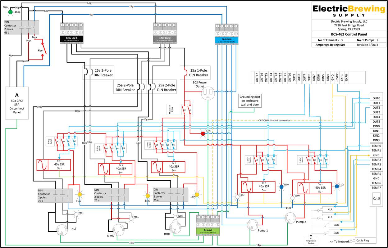
I'm planning to build a BCS462-based RIMS system with 3 4500W elements. Obviously I can't fire more than 2 elements simultaneously on a 50A circuit, but the schematic I'm using appears to allow all 3 elements to fire in either Manual or Auto modes. I'd like to set it up to only allow the RIMS or the BK element to be on at one time, while still allowing safe manual control and safe BCS control. Obviously another switch will be needed, but how and where should it be wired in the diagram? I'm pretty good at following logic, but when 3-position switches (OFF/AUTO/MANUAL and AUTO/RIMS/BK) are in use I start to feel like I'm playing that crazy 3D chess game in Star Trek and my brain melts down.

I could include the Visio document if that would make it easier.

Thanks!
mctxUXl.gif
 
Before we get into some awesome reconfiguring, lets look at what you need. If you size your elements correctly then you may be able to get away with not even worrying about it.

What if you used a 3k watt element for your HLT, and a 3k watt element for your RIMS? At 50 amps you should have a total power of roughly 12000 watts, but of course that is really pushing it. If all three elements are at 4500 watts then your total power for those alone would be 13.5k watts. If you reduce your total power of two of the elements to 3k though then your total power consumption for the elements would be 10.5k watts. Which would leave enough room for a couple pumps, lights, and your controller.

[edit]
To directly answer your question if you can get a 2 pole switch where each of the poles are opposite each other. EG one is open while the other is closed, and vice versa. Then you can just intercept the low voltage side of the SSRs to each respective element and all will be right as rain. I'm sorry, I know those switches are easily accessible but I haven't taken the time to find an example for you.

So it looks like out 1 and out 2 off the terminal block on the right of the diagram would be the wires your would intercept and add the switch into. So many switches!

Hopefully I am correct here. Just want to help
 
Back
Top