You are using an out of date browser. It may not display this or other websites correctly.
You should upgrade or use an alternative browser.
You should upgrade or use an alternative browser.
Electric Noob starting E-brewery. Help pls!
- Thread starter Cacaman
- Start date

Help Support Homebrew Talk:
This site may earn a commission from merchant affiliate
links, including eBay, Amazon, and others.


BeerguyNC61
Well-Known Member
Did you use the tubing to hold on to the lid?
BeerguyNC61 said:Did you use the tubing to hold on to the lid?
Not at all. I just used that little piece of cardboard circle to guide me in a circle, I didn't bind it to the angle grinder with a hose clamp or anything, just used my hand (my wrist was extremely tired after this). Once I felt the lid was loose, I simply stopped grinding, gave it a slight tap, and the lid fell right in the keg. One down, one to go
")
Another important component in, my enclosure!


It's a 16x16x12 metal enclosure from pioneer breaker. Now I know a lot of people say to stay away from this site, but this is just a metal box, I don't know how anyone can counterfeit that.
I wanted a 16x16x8, but they were sold out and didn't want to wait until November for this. Bigger won't do me any harm now would it?
Both kegs cut now, just need to sand down the edges. I think I got a slightly larger cut from today's cut (left), but that doesn't really matter to me. Will post more pics of kegs when cleaned up well and holes, valves, tubes etc. have been made.


$53.24
1pc Hose Barb/MFL 1.5" Tri Clamp to Ball Lock Post Liquid Gas Homebrew Kegging Fermentation Parts Brewer Hardware SUS304(Gas Hose Barb)
Guangshui Weilu You Trading Co., Ltd

$479.00
$559.00
EdgeStar KC1000SS Craft Brew Kegerator for 1/6 Barrel and Cornelius Kegs
Amazon.com


$7.79 ($7.79 / Count)
Craft A Brew - LalBrew Voss™ - Kveik Ale Yeast - For Craft Lagers - Ingredients for Home Brewing - Beer Making Supplies - (1 Pack)
Craft a Brew


$176.97
1pc Commercial Keg Manifold 2" Tri Clamp,Ball Lock Tapping Head,Pressure Gauge/Adjustable PRV for Kegging,Fermentation Control
hanhanbaihuoxiaoshoudian

$28.98
Five Star - 6022b_ - Star San - 32 Ounce - High Foaming Sanitizer
Great Fermentations of Indiana

$719.00
$799.00
EdgeStar KC2000TWIN Full Size Dual Tap Kegerator & Draft Beer Dispenser - Black
Amazon.com

$172.35
2 Inch Tri Clamp Keg Manifold With Ball Lock Posts, Pressure Gauge, PRV (0-30 PSI) – Homebrew, Fermentation, Kegging System
wuhanshijiayangzhiyimaoyiyouxiangongsi

$20.94
$29.99
The Brew Your Own Big Book of Clone Recipes: Featuring 300 Homebrew Recipes from Your Favorite Breweries
Amazon.com
![Craft A Brew - Safale BE-256 Yeast - Fermentis - Belgian Ale Dry Yeast - For Belgian & Strong Ales - Ingredients for Home Brewing - Beer Making Supplies - [3 Pack]](https://m.media-amazon.com/images/I/51bcKEwQmWL._SL500_.jpg)


$159.99 ($26.66 / Count)
3M High Flow Series System BREW120-MS, 5616001, For Brewed Coffee and Hot Tea, Valve-in-Head Design
SpaceCityProviders

$53.24
1pc Hose Barb/MFL 1.5" Tri Clamp to Ball Lock Post Liquid Gas Homebrew Kegging Fermentation Parts Brewer Hardware SUS304(Liquid Hose Barb)
yunchengshiyanhuqucuichendianzishangwuyouxiangongsi


$44.99
$49.95
Craft A Brew - Mead Making Kit – Reusable Make Your Own Mead Kit – Yields 1 Gallon of Mead
Craft a Brew


$76.92 ($2,179.04 / Ounce)
Brewing accessories 1.5" Tri Clamp to Ball Lock Post Liquid Gas Homebrew Kegging Fermentation Parts Brewer Hardware SUS304 Brewing accessories(Gas Hose Barb)
chuhanhandianzishangwu


$33.99 ($17.00 / Count)
$41.99 ($21.00 / Count)
2 Pack 1 Gallon Large Fermentation Jars with 3 Airlocks and 2 SCREW Lids(100% Airtight Heavy Duty Lid w Silicone) - Wide Mouth Glass Jars w Scale Mark - Pickle Jars for Sauerkraut, Sourdough Starter
Qianfenie Direct


$10.99 ($31.16 / Ounce)
Hornindal Kveik Yeast for Homebrewing - Mead, Cider, Wine, Beer - 10g Packet - Saccharomyces Cerevisiae - Sold by Shadowhive.com
Shadowhive


$22.00 ($623.23 / Ounce)
AMZLMPKNTW Ball Lock Sample Faucet 30cm Reinforced Silicone Hose Secondary Fermentation Homebrew Kegging joyful
无为中南商贸有限公司

$58.16
HUIZHUGS Brewing Equipment Keg Ball Lock Faucet 30cm Reinforced Silicone Hose Secondary Fermentation Homebrew Kegging Brewing Equipment
xiangshuizhenzhanglingfengshop


Cacaman said:It's a 16x16x12 metal enclosure
You will be glad for the extra workspace. Mine was upgraded to 20x20x8 and I am really glad.
You will be glad for the extra workspace. Mine was upgraded to 20x20x8 and I am really glad.
Hope so!

Quick question, since im pretty much replicating Kal's build, will any of these SSR's work: http://stores.ebay.com/jamesbondtb/_i.html?_nkw=40a+ssr&submit=Search&_sid=1064500270 ?
Preferably one without a heatsink, im thinking the third one on that list.
I notice on kal's site he recommends output voltage to be 90-480VAC, and the ones on that link are only 24-380VAC, will this be an issue? My heating elements are the "Camco #02963 5500W 240VAC ultra low watt density (ULWD) RIPP element".
Thanks!
In that case, I'll order them from Auber.
Also, do you all think these relays will work?
http://www.ebay.com/itm/30062983238...l?_sacat=0&_from=R40&_nkw=300629832383&_rdc=1
If not, will any of these work?
http://stores.ebay.com/jamesbondtb/...ubmit=Search&_fsub=2574799010&_sid=1064500270
Thanks so much!
Edit: Reason why I ask about the ones on that first link is because I thought they were a good deal and ordered them impulsively :cross:. Anyways I put the order on hold until i can confirm they work, or so that i can order the proper ones. Thanks!
Just get the right one in the first place:
Contactor, 2 pole, 30A, 120V Coil
Contactor, 2 pole, 30A, 120V Coil
P-J said:Just get the right one in the first place:
Contactor, 2 pole, 30A, 120V Coil
Thanks! That was really ignorant of me

That's hot....or at least it will be with some ssr action!
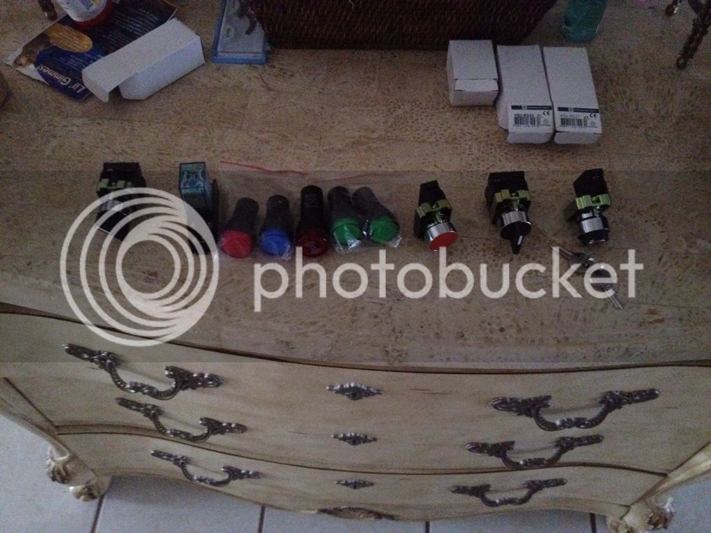
Hey guys, I've been on a temporary hiatus but I'm pleased to say that I am back in business. At this point I have all the parts needed to complete my control panel. Here are some photos of my latest progress.
Here is the top part JB welded and the screws sanded down. I just used an angle grinder instead of filing them down.
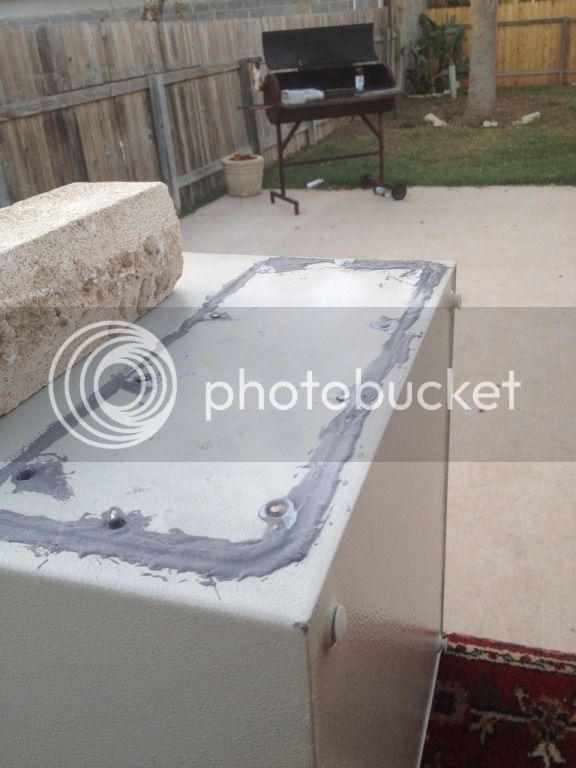
Here is the top part JB welded and the screws sanded down. I just used an angle grinder instead of filing them down.
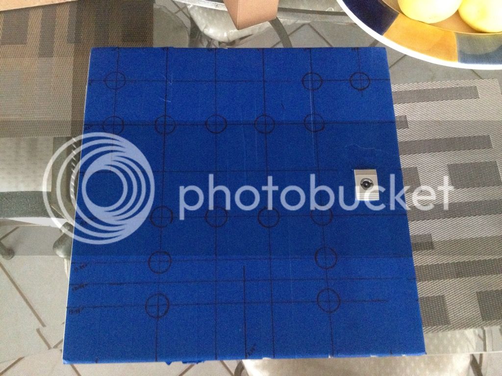
If you haven't drilled them yet, make sure you have clearance for the devices you plan for the two holes in the upper left hand portion of your control panel. It looks like they are very close to the hinges.
If you haven't drilled them yet, make sure you have clearance for the devices you plan for the two holes in the upper left hand portion of your control panel. It looks like they are very close to the hinges.
Excellent point. As a matter of fact, i was walking inside my house from drilling the holes when i read this comment. Doh! I reconnected my door and hinges, and attached the blue light and key switch. Fortunate enough, it cleared by no more than a few millimeters. Phew! Thanks for the heads up though!


If you haven't drilled them yet, make sure you have clearance for the devices you plan for the two holes in the upper left hand portion of your control panel. It looks like they are very close to the hinges.
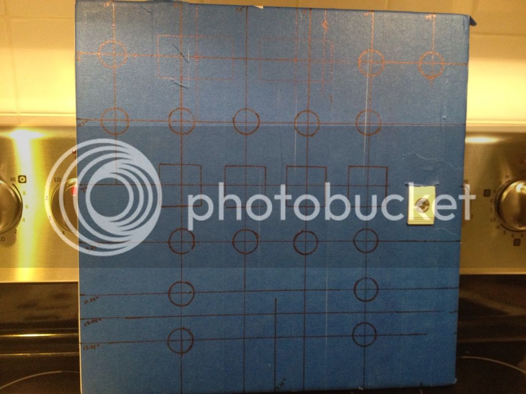
I guess its too late but for the sake of others who read this before drilling, it isnt just about leaving space for the hinges & rubber seal.
You also need space for the wiring, which will come straight out of the component and cant turn for at least 1/2" My door barely closes without rubbing on the wire.
All front plate holes have been drilled now. Here are some photos


They are less than perfect, but have been test fitted and work fine. For the right voltmeter, I didn't have to add a second slot, it fit snugly like that. That's enough work for a Friday night, now to go out and have a beer on tap


They are less than perfect, but have been test fitted and work fine. For the right voltmeter, I didn't have to add a second slot, it fit snugly like that. That's enough work for a Friday night, now to go out and have a beer on tap

Got a question though, will this:
http://www.auberins.com/index.php?main_page=product_info&cPath=2_31&products_id=129
be able to be used as the "30A/240V DPDT or DPST relay with 120V AC coil" that kal uses in his build? Or are we looking at totally different parts?
http://www.auberins.com/index.php?main_page=product_info&cPath=2_31&products_id=129
be able to be used as the "30A/240V DPDT or DPST relay with 120V AC coil" that kal uses in his build? Or are we looking at totally different parts?
jeffmeh
Well-Known Member
- Joined
- Feb 26, 2009
- Messages
- 2,145
- Reaction score
- 216
Got a question though, will this:
http://www.auberins.com/index.php?main_page=product_info&cPath=2_31&products_id=129
be able to be used as the "30A/240V DPDT or DPST relay with 120V AC coil" that kal uses in his build? Or are we looking at totally different parts?
Yes indeed.
Ok, now this is going to sound dumb, but Kal's relay has 6 "attachment points" whereas the one i linked appears to only have 4. Here is a picture to better explain what i mean:
Am I missing something? (besides brains :cross: )

Am I missing something? (besides brains :cross: )
jeffmeh
Well-Known Member
- Joined
- Feb 26, 2009
- Messages
- 2,145
- Reaction score
- 216
Ok, now this is going to sound dumb, but Kal's relay has 6 "attachment points" whereas the one i linked appears to only have 4. Here is a picture to better explain what i mean:
Am I missing something? (besides brains :cross: )
Kal's is a double pole double throw contactor, though he is only using one throw. It likely has 8 attachment points.
The one you linked to is a double pole single throw contactor (perfectly suitable). It will have 6 attachment points, whether or not you can see them in the picture:
1) Line for H1
2) Line for H2
3) Load for H1
4) Load for H2
5) Coil for H1
6) Coil for N


Nope. On the sides, here.

Hmmmm cank, that doesn't seem right. There's no place for the terminal to go


On the bottom though, there's a screw that opens a spot for a terminal maybe

If this is the case, now to figure out which is
1) Line for H1
2) Line for H2
3) Load for H1
4) Load for H2
5) Coil for H1 (may be interchangeable as per stlbeer)
6) Coil for N (may be interchangeable as per stlbeer)


On the bottom though, there's a screw that opens a spot for a terminal maybe

If this is the case, now to figure out which is
1) Line for H1
2) Line for H2
3) Load for H1
4) Load for H2
5) Coil for H1 (may be interchangeable as per stlbeer)
6) Coil for N (may be interchangeable as per stlbeer)
You are looking at the coil in this picture. The shiny orange part is the coil for pulling the relay closed. There are 2 spade terminal connections there so they can be easily daisy chained together (you probably don't need that though).
If this is the case, now to figure out which is
1) Line for H1
2) Line for H2
3) Load for H1
4) Load for H2
5) Coil for H1 (may be interchangeable as per stlbeer)
6) Coil for N (may be interchangeable as per stlbeer)
On each side, where there are multiple YELLOW spade and screw connections, these are your Line and Load. Pick one side to be Line and one side to be load. Test these with your multi-meter after you have hooked up the coil connections and are able to test the relay BEFORE hooking up other wires. The relay does not care which side is line or load.
You have a multi-meter, right?
That screw on the bottom looks like its for mounting the relay to the plate.
Paul
Similar threads
- Replies
- 20
- Views
- 849
- Replies
- 6
- Views
- 856
- Replies
- 37
- Views
- 3K
